
Translate this page into:
3T Magnetic Resonance Imaging of the Thumb-normal Appearances and Common Injuries

Corresponding author: Nivedita Chakrabarty, Department of Radiology, Innovision Imaging, Mumbai, Maharashtra, India. dr.niveditachakrabarty@gmail.Com
-
Received: ,
Accepted: ,
How to cite this article: Chakrabarty N, Daftary A, Lawande M. 3T Magnetic Resonance Imaging of the Thumb-normal Appearances and Common Injuries. Indian J Musculoskelet Radiol 2020;2(1):44-51.
Abstract
Thumb is unique not only in its orientation and function compared to the other fingers but also in its bony and soft-tissue anatomy. It is important to understand methods to acquire appropriate image of the thumb along its axis, become familiar with the normal magnetic resonance imaging anatomy of the thumb and develop an understanding of the appearance of common injuries, all of which help in proper management. With proper scanning technique, it is possible to identify all the ligaments, tendons, and pulleys of the thumb. Checklist ensures that all the structures are systematically seen and injuries are consciously looked for in a case of thumb trauma.
Keywords
Thumb axis
Magnetic resonance imaging anatomy
Checklist
Thumb injuries

INTRODUCTION
In this pictorial review, we will discuss the basic tenets of optimal image acquisition, including positioning, sequences, and other technical parameters. We will demonstrate the appearance of the normal structures, common injury patterns to the carpometacarpal (CMC), metacarpophalangeal (MCP), and interphalangeal (IP) joints as well as the flexor and extensor tendons and demonstrate their appearance. Finally, we will discuss the relevance of these findings in relation to clinical management.
The checklist should include: Bones, ligaments, volar and dorsal plates, tendons, adductor aponeurosis, and pulleys so that all the structures are systematically evaluated. In this pictorial review, we will focus on the anatomy and injuries of the soft-tissue structures of the thumb.
MR SEQUENCES AND PLANNING
We have a 3T Magnetic Resonance Imaging (MRI) and use a dedicated hand coil for obtaining high resolution images of thumb. The thumb axis is taken as the trapeziometacarpal (TMC) joint in approximately 80 degrees pronation and flexion with respect to the other metacarpals.[1]
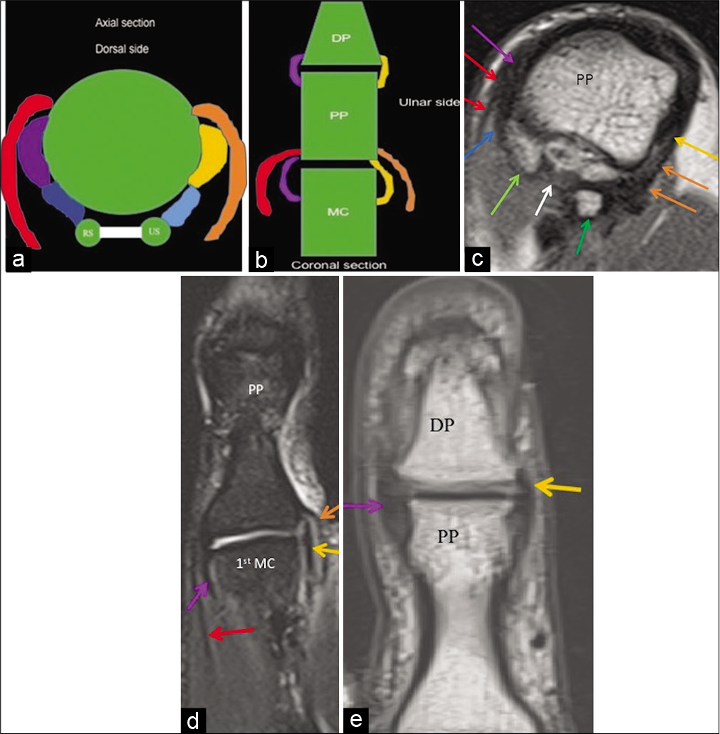
[Figure 1a] shows the thumb axis along the TMC joint to the distal phalanx. We obtain coronal images parallel to the widest axial dimension of the proximal phalanx, followed by sagittal images perpendicular to the coronal image [Figures 1b-d]. Proton density fast spin echo (PD FSE) and T2-weighted images (with and without fat saturation), each in axial, coronal, and sagittal planes of the thumb are the sequences used with 2 mm slice thickness. We use 320 × 320 matrix with a field of view of 130 mm on sagittal and coronal planes and 80 mm in the axial plane on 3T MRI.

- Thumb magnetic resonance imaging sequence planning. (a) Localizer image along the trapeziometacarpal joint shows the thumb axis (blue line). (b) Axial PD FSE image through the widest diameter of the proximal phalanx; blue lines show the plane along which coronal images will be obtained. (c) Coronal PD FSE image from the trapeziometacarpal joint to the distal interphalangeal joint; blue lines show the plane along which sagittal images will be obtained. (d) Sagittal PD FSE image from the trapeziometacarpal joint to the distal interphalangeal joint.
ANATOMY
Ligaments
The following five ligaments are imperative for stabilizing the TMC joint: (a) The anterior oblique ligament (AOL) (both portions; superficial [AOLs] and deep [AOLd]), (b) posterior oblique ligament (POL), (c) ulnar collateral ligament (UCL), (d) dorsoradial ligament (DRL), and (e) intermetacarpal ligament (ICL).[2] The DRL, POL, ICL, and AOL are best evaluated in the sagittal plane [Figures 2-5], whereas the UCL is best demonstrated in the coronal plane [Figure 6].[2]
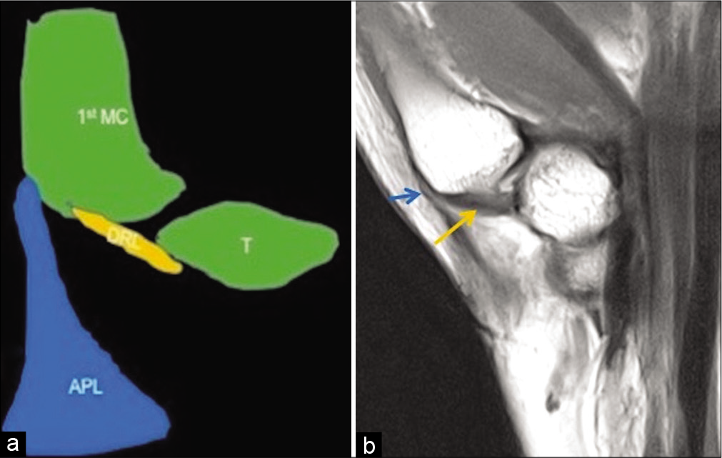
- Anatomy of the dorsoradial ligament. Schematic representation (a) and PD FSE sagittal image (b) of the trapeziometacarpal joint show the dorsoradial ligament (yellow colored structure in a and yellow arrow in b) extending from the trapezium to the dorsal edge of the base of thumb metacarpal proximal to the distal attachment of the abductor pollicis longus tendon (blue colored structure in a and blue arrow in b) on the lateral side of first metacarpal.
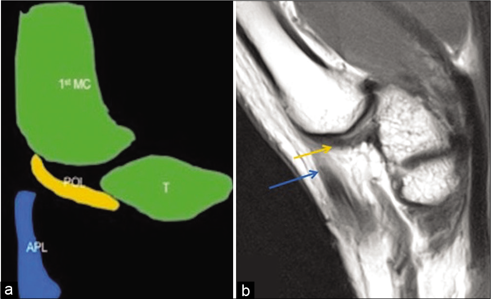
- Anatomy of the posterior oblique ligament. Schematic representation (a) and PD FSE sagittal image (b) of the trapeziometacarpal joint show the posterior oblique ligament (yellow colored structure in a and yellow arrow in b) extending from the dorsal side of trapezium to the dorsal base of first metacarpal; at this level, the distal attachment of the abductor pollicis longus tendon (blue colored structure in a and blue arrow in b) is no longer visible.
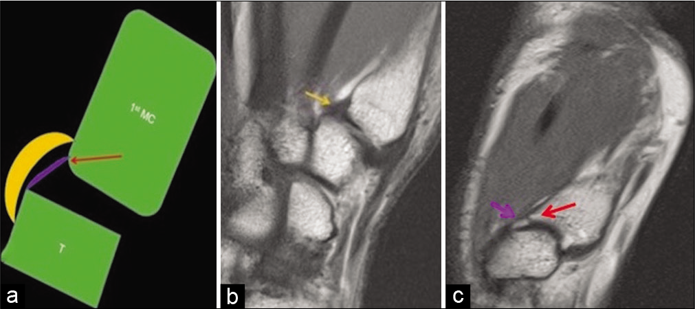
- Anatomy of the superficial and deep anterior oblique ligaments. Schematic representation (a) and PD FSE sagittal images (b and c) of the trapeziometacarpal joint show the superficial anterior oblique ligament (yellow colored structure in a and yellow arrow in b) extending from the volar tubercle of the trapezium, proximal to the first carpometacarpal joint to the volar tubercle of the first metacarpal. The shorter intra-articular deep anterior oblique ligament (purple colored structure in a and purple arrow in c) extends from the articular margins of the trapezium to the “beaked” volar base of the first metacarpal (red arrow in a and c).
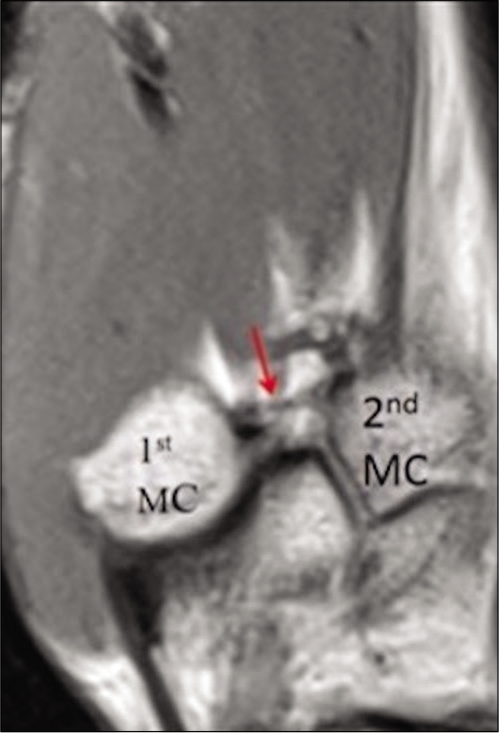
- Anatomy of the intermetacarpal ligament. Sagittal PD FSE image shows the intermetacarpal ligament (red arrow) extending from the dorsoradial aspect of the second metacarpal to the volar- ulnar tubercle of the first metacarpal base.

- Anatomy of the ulnar collateral ligament at the carpometacarpal joint level: Coronal PD image of the wrist shows the ulnar collateral ligament (yellow arrow) arising from the trapezial ridge attachment of the flexor retinaculum.
At the level of MCP and IP joints, there are proper and accessory UCL [Figures 7a-e].[3]
- Proper and accessory radial and ulnar collateral ligaments at the metacarpophalangeal and interphalangeal joint levels. (a) Schematic axial representation at the metacarpophalangeal joint level shows proper radial collateral ligament (purple colored structure) and proper ulnar collateral ligament (yellow colored structure), volar plate (white colored structure) connecting the radial (RS) and ulnar (US) sesamoid bones. Also shown are the accessory radial collateral ligament (dark blue colored structured) and accessory ulnar collateral ligament (light blue colored structure) attaching to the radial and ulnar sesamoids respectively. Aponeurosis of adductor pollicis tendon (orange colored structure) and abductor pollicis brevis tendon insertion (red colored structure) overlay the ulnar and radial collateral ligaments, respectively. (b) Schematic coronal representation shows proper radial collateral ligament (purple colored structure) and proper ulnar collateral ligament (yellow colored structure) at both metacarpophalangeal and interphalangeal joint levels. Aponeurosis of adductor pollicis tendon (orange colored structure) and abductor pollicis brevis tendon insertion (red colored structure) overlay the ulnar and radial collateral ligaments, respectively. (c) Axial PD FSE image shows proper radial collateral ligament (purple arrow) and proper ulnar collateral ligament (yellow arrow), volar plate (white arrow) connecting the radial (light green arrow), and ulnar (dark green arrow) sesamoid bones and accessory radial (dark blue arrow) collateral ligament attaching to the radial sesamoid (light green arrow). Abductor pollicis brevis tendon insertion (red arrow) overlay the radial collateral ligament and adductor pollicis aponeurosis (orange arrow) overlay the ulnar collateral ligament. (d) Coronal T2 fat saturated image shows proper radial collateral ligament (purple arrow) and proper ulnar collateral ligament (yellow arrow) at the metacarpophalangeal joint. Aponeurosis of adductor pollicis tendon (orange arrow) and abductor pollicis brevis tendon insertion (red arrow) overlay the ulnar and radial collateral ligaments respectively. (e) Coronal PD FSE image shows the radial collateral ligament (purple arrow) and ulnar collateral ligament (yellow arrow) at the interphalangeal joint level.
VOLAR AND DORSAL PLATES
Volar and dorsal plates [Figures 8a and b] are fibro- cartilaginous structures which surround the first MCP and IP joints and strengthen the joint capsule.[3] Volar plates are more important than dorsal plates for providing joint stability and hence are of greater concern during injury.[4]
- Volar and dorsal plates. (a) Sagittal PD FSE image shows the volar plate (purple arrow and dorsal plate (yellow arrow) at the interphalangeal and metacarpophalangeal joints respectively. (b) Axial PD FSE image shows the volar plate (purple arrow) at the interphalangeal joint.
TENDONS AND APONEUROSIS
The abductor pollicis brevis tendon overlies the radial collateral ligament and inserts at the radial base of the proximal phalanx of the thumb [Figures 7a-d].[4] Some adductor pollicis fibers insert on the ulnar sesamoid bone, while others form the adductor aponeurosis and continue distally superficial to the UCL and then insert on the proximal phalanx [Figures 7a-d].[4]
Palmarly, the flexor pollicis longus (FPL) tendon lies between the two sesamoid bones superficial to the volar plate and inserts at the distal phalanx base [Figures 9a-c].[4]

- Flexor pollicis longus, extensor pollicis longus and brevis tendon insertions. (a) Sagittal schematic representation shows flexor pollicis longus tendon (blue colored structure) attachment to the volar aspect of the distal phalangeal base. Extensor pollicis brevis tendon (orange colored structure) and extensor pollicis longus tendon (yellow colored structure) attach to the dorsal aspects of the proximal and distal phalangeal bases respectively. Extensor pollicis brevis tendon is seen to blend with the dorsal plate (red colored structure) with presence of a synovial recess (purple arrow) underlying it. (b) Sagittal PD FSE shows flexor pollicis longus tendon (blue arrow) and extensor pollicis longus tendon (yellow arrow) attaching to the volar and dorsal aspects of the distal phalangeal base respectively. (c) Axial PD FSE shows flexor pollicis longus tendon (blue arrow) and extensor pollicis longus tendon (yellow arrow) at the level of interphalangeal joint. (d) Sagittal PD FSE image at the metacarpophalangeal joint level shows extensor pollicis brevis tendon (orange arrow) attaching to the dorsal aspect of the proximal phalangeal base and blending with the dorsal plate (red arrow). A synovial recess (purple arrow) is seen underlying the dorsal plate and extensor pollicis brevis insertion. Extensor pollicis longus tendon (yellow arrow) is seen continuing distally.
Dorsally, the extensor pollicis brevis (EPB) tendon blends with the dorsal plate of the first MCP joint and inserts on the dorsal proximal phalanx base [Figures 9a and d].[4] The EPB tendon lies on the radial side of the extensor pollicis longus (EPL) tendon proximal to the first MCP joint.[4] The EPL tendon continues distally and inserts onto the dorsal base of the distal phalanx [Figures 9 a-d].[4]
PULLEYS
[Figure 10a-c] shows location, radial, and ulnar limbs of the annular pulleys. The thumb has only annular pulleys without any cruciform pulleys.[4]

- Pulleys. (a) Sagittal schematic representation shows first annular pulley (A1) at the level of metacarpophalangeal joint, variable annular pulley (Av) at the level of proximal phalangeal base, oblique annular pulley (Ao) at the level of diaphysis of proximal phalanx and second annular pulley (A2) at the level of interphalangeal joint. Axial schematic representation (b) and axial PD FSE image (c) show the radial limb (purple colored structure in b and purple arrow in c) and ulnar limb (orange colored structure in b and orange arrow in c) of the annular pulley holding the flexor pollicis longus tendon (red colored structure in b and red arrow in c) in place.
COMMON INJURIES AND THEIR BIOMECHANICS ALONG WITH IMAGING FINDINGS AND IMPLICATION ON TREATMENT
Injury patterns to the thumb can be divided into those of the (a) CMC joint ligaments (commonly injured-anterior oblique and dorsoradial ligaments), MCP, and IP joint collateral ligaments, (b) flexor or extensor tendons, (c) pulleys, and (d) volar/palmar plates.
Biomechanical patterns include varus, valgus, hyperextension, strong flexion, and forced flexion during active extension and axial loading with flexion of thumb metacarpal base. Table 1 shows the structures which are injured on the basis of the biomechanics.
| Biomechanical patterns→Structures injured ↓ | Varus force | Valgus force | Hyperextension | Strong flexion | Forced flexion during active extension | Axial loading with flexionof thumb metacarpal base |
|---|---|---|---|---|---|---|
| At the carpometacarpal joint level | Anterior oblique ligament Dorsoradial ligament |
|||||
| At the metacarpophalangeal joint level | Radial collateral ligament | Ulnar collateral ligament | Volar plate Flexor pollicis longus tendon |
Pulleys | Extensor pollicis brevis tendon Extensor pollicis longus tendon |
|
| At the interphalangeal joint level | Radial collateral ligament | Ulnar collateral ligament | Volar plate Flexor pollicis longus tendon |
Pulleys | Extensor pollicis longus tendon |
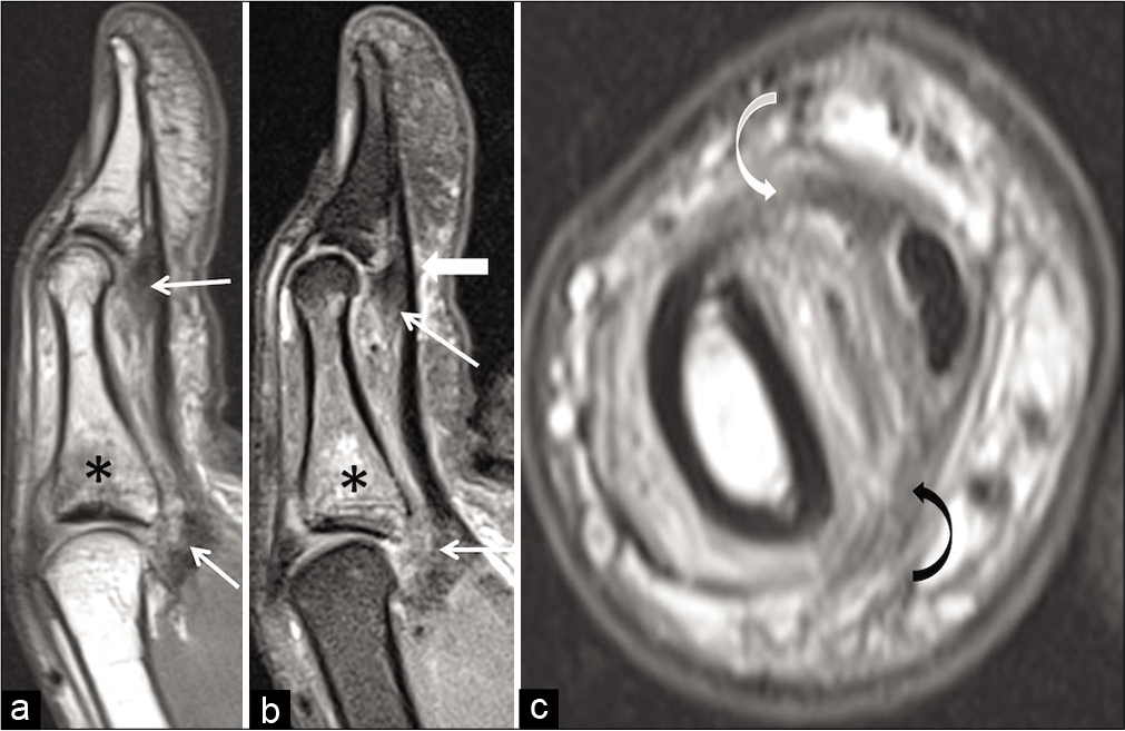
UCL injury at the MCP joint of the thumb is very common and occurs due to valgus stress on an abducted thumb.[5] A Stener lesion occurs when the UCL is completely torn from its proximal phalangeal base attachment, is retracted, and lies superficial and proximal to the adductor pollicis aponeurosis as seen in the coronal T2 fat saturated and coronal PD FSE images at the MCP joint [Figures 11a and b].[5] Non Stener lesion is when the torn UCL maintains its position deep to the adductor pollicis aponeurosis as seen in the coronal PD FSE image at the MCP joint [Figure 12]. Stener lesion requires operative management as the interposition of the adductor aponeurosis prevents healing whereas non Stener lesion is managed conservatively with immobilization in a short arm-thumb spica cast for 4 weeks.[5]
- Stener lesion following valgus force injury to the metacarpophalangeal joint. Coronal T2 fat saturated (a) and coronal PD FSE (b) images show completely torn ulnar collateral ligament (curved black arrow) lying superficial to the adductor pollicis aponeurosis (straight white arrow).

- Non-Stener lesion following valgus force injury to the metacarpophalangeal joint. Coronal PD FSE image shows completely torn proximal phalangeal attachment of ulnar collateral ligament (curved white arrow) with the adductor pollicis aponeurosis (straight white arrow) lying superficial to the proximally retracted ulnar collateral ligament.
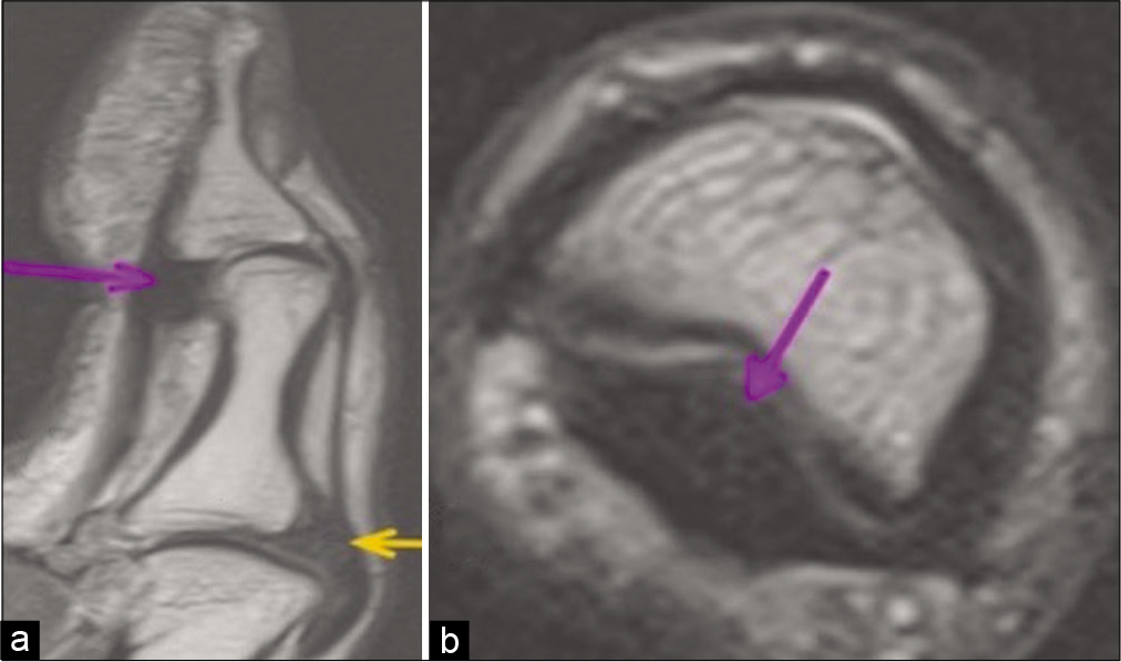
Volar plate injuries occur due to hyperextension force [Figures 13a-c] and are avulsion fractures usually accompanied by phalangeal base fractures.[6] Pulley injury of thumb is an uncommon injury and occurs during strong flexion.[6,7] Sagittal PD FSE and sagittal T2 fat saturated images show volar plate injury suggested by altered signal intensity along with proximal phalangeal base edema suggestive of fracture in the setting of trauma [Figures 13a and b]. When the sagittal image [Figure 13b] shows that the FPL tendon is not closely apposed to the underlying phalanx(bowstringing), then it suggests injury to the pulley which is confirmed on axial image [Figures 13c]. Volar plate injury is reported as per the Eaton classification based on the size and the degree of comminution of the intra articular fragments and the percentage of articular surface involved, as it helps in deciding the management.[8,9] Based on Eaton classification, stable closed reduction is performed for small intra-articular fragments involving <25–40% of the articular surface and with greater involvement of the articular surface, the treatment depends on the degree of comminution of the intra-articular fragment.[8,9]
- Volar plate and pulley injuries due to hyperextension force and strong flexion respectively. Sagittal PD FSE (a) and sagittal T2 fat saturated (b) images show volar plate injury (thin white arrow) at the metacarpophalangeal joint and interphalangeal joint along with proximal phalangeal base edema (asterisk). Mild bowstringing of the flexor pollicis longus tendon (thick arrow in b) suggests annular pulley injury. (c) Axial PD FSE image shows stretch injury to both the radial (curved white arrow) and ulnar limb (curved black arrow) of the annular pulley.
Radial collateral ligament injury occurs due to forced adduction on a flexed MCP joint.[10] Grades 1 and 2 injuries with maintained ligament continuity are usually managed conservatively while Grade 3 injuries with discontinuity may require surgical management.[11] Coronal PD FSE image at the MCP joint [Figure 14] shows Grade 3 injury to the radial collateral ligament.
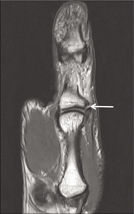
- Radial collateral ligament injury due to the varus force. Coronal PD FSE image at the metacarpophalangeal joint shows completely torn radial collateral ligament (straight white arrow) from its phalangeal attachment.
EPL and brevis tendon injuries occur due to forced flexion during active extension or penetrating trauma and lacerations. Extensor tendon injuries are divided into various zones.[12] A zone wise description of the extensor tendon injury is useful in surgical planning.[13] Flexor tendon injuries which occur due to hyperextension forces or penetrating injuries are also divided into various zones and managed as per the zone wise location of the injured tendon.[13] Figure 15 depicts the various zones of extensor and flexor tendon injuries schematically. The zones of extensor and flexor tendon injuries are depicted on sagittal images. Figures 16a and b shows complete rupture of EPL tendon with the tendon retracted to the level of proximal phalanx in keeping with zone II injury.

- Zones of flexor and extensor injuries. Zones TI, TII and TIII refer to zones of flexor tendon injuries distal to IP joint, from A1 pulley to IP joint and at the thenar eminence respectively. Zones I to V refer to zones of extensor tendon injuries as follows: Zone I: Disruption of EPL at interphalangeal joint. Zone II: Disruption of EPL at proximal phalanx. Zone III: Disruption of EPL and EPB at metacarpophalangeal joint. Zone IV: Disruption of EPL and EPB at metacarpal. Zone V: Disruption of EPL and EPB at carpometacarpal joint.

- Extensor pollicis longus tendon injury due to hyperflexion force. Sagittal PD FSE (a) and axial PD FSE (b) images show completely ruptured extensor pollicis longus tendon (straight black arrow) at the level of the proximal phalanx in keeping with zone II injury.
Figure 17a and b shows completely ruptured FPL tendon with the tendon retracted to the level of MCP joint in keeping with zone T II injury.

- Flexor pollicis longus tendon injury due to hyperextension force. Sagittal PD FSE (a) and axial PD FSE (b) images show completely ruptured flexor pollicis longus tendon (straight black arrow) with the tendon retracted to the level of metacarpophalangeal joint in keeping with zone T II injury.
The most common TMC joint ligament injury mechanism is axial loading with flexion of the thumb metacarpal base.[14]
The AOL (beak ligament) is the most commonly injured, usually at the distal attachment.[15] The dorsal radial ligament may show avulsion or partial tear at the trapezoid attachment.[15]
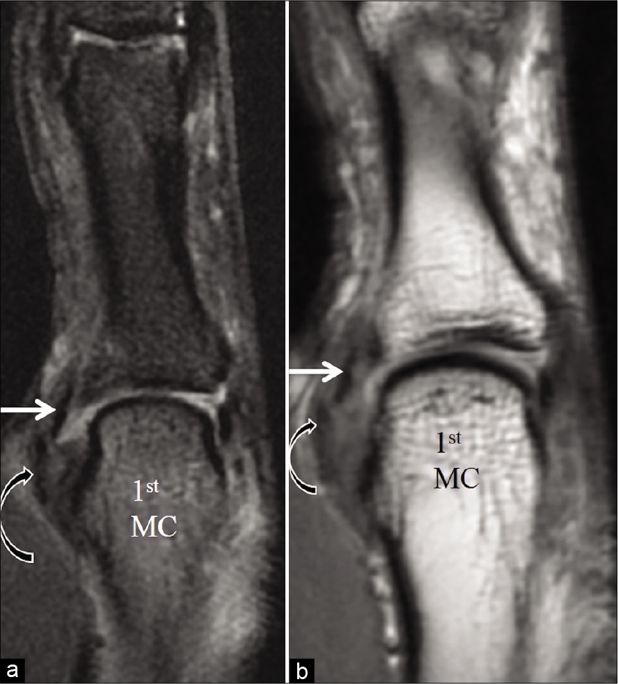
Bennett fracture, which is a non-comminuted intra- articular fracture of the first metacarpal base, is the most common injury of the thumb CMC joint and is usually associated with first metacarpal dorsal subluxation or dislocation.[16] In Bennett fracture-dislocation injuries, the deep AOL attachment to the proximal ulnar metacarpal fragment remains intact, leading to an osseous fragment from the volar aspect of the metacarpal base [Figure 18], while the rest of the metacarpal is pulled radially by the APL.[4] If there is no dislocation or any signs of clinical or radiological instability, then, conservative management with thumb spica cast for 4–6 weeks is recommended in case of acute post-traumatic painful joint.[10] Figure 18 shows Bennett fracture with stretch injury of the anterior oblique (beak) ligament.

- Bennett fracture with stretch injury of the deep anterior oblique (beak) ligament. Sagittal T2W fat saturated (a) and CT scan (b) images show Bennett fracture (thick white arrow) from the palmar aspect of the first metacarpal base at the attachment of the deep anterior oblique ligament (beak ligament) which is stretched and thickened (thin white arrow in a).
DRL injury is best depicted in the sagittal images of the TMC joint and this ligament is usually torn from its trapezoid attachment [Figure 19].
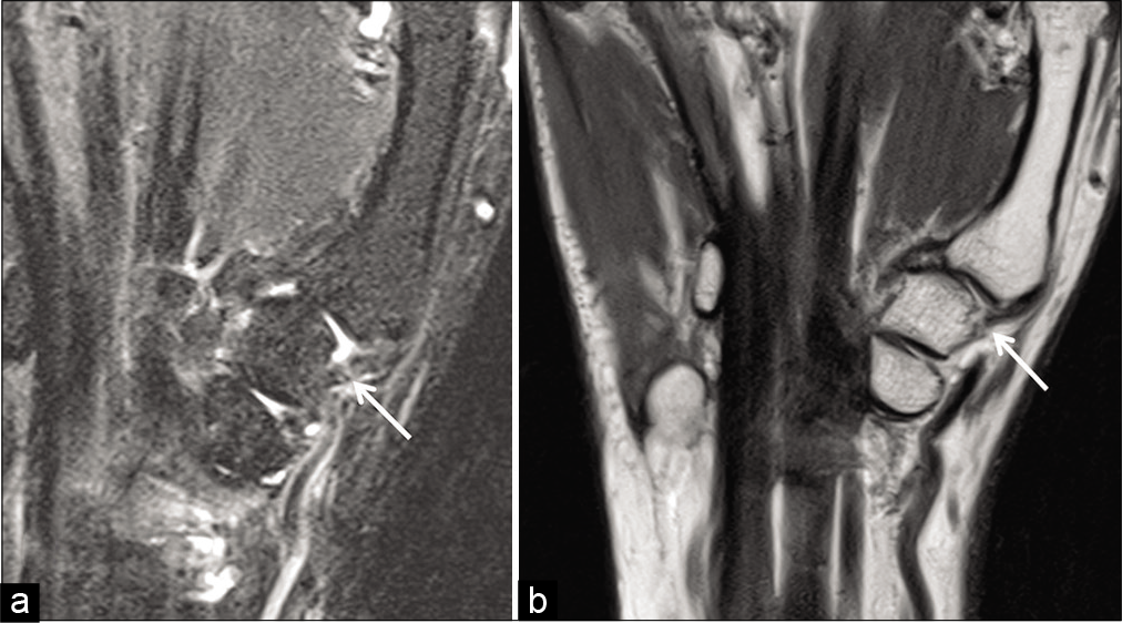
- Dorsoradial ligament injury. Sagittal T2 fat saturated image (a) and sagittal PD FSE image (b) of the trapeziometacarpal joint show completely torn dorsoradial ligament (white arrow) form its trapezoid attachment.
CONCLUSION
Appropriate high resolution imaging, an understanding of the normal and abnormal MRI appearance of the structures along with an understanding of the biomechanics and implications in the management of thumb injuries is important in clinically relevant interpretation of these scans.
Acknowledgment
First author, who is also the corresponding author, has presented this article as an e-poster and won the third prize in the National Musculoskeletal Society (MSS) conference held in Pune in August 2019.
Declaration of patient consent
Patient’s consent not required as patients identity is not disclosed or compromised.
Financial support and sponsorship
Nil.
Conflicts of interest
There are no conflicts of interest.
References
- Imaging the ligaments of the trapeziometacarpal Joint: MRI compared with MR arthrography in cadaveric specimens. AJR Am J Roentgenol. 2009;192:W13-9.
- [CrossRef] [PubMed] [Google Scholar]
- MRI of the thumb: Anatomy and spectrum of findings in asymptomatic volunteers. AJR Am J Roentgenol. 2014;202:819-27.
- [CrossRef] [PubMed] [Google Scholar]
- High-resolution MR imaging and US anatomy of the thumb. Radiographics. 2016;36:1701-16.
- [CrossRef] [PubMed] [Google Scholar]
- Injuries to the Ulnar Collateral Ligament of the Thumb Metacarpophalangeal Joint. J Am Acad Orthop Surg. 1997;5:224-9.
- [CrossRef] [PubMed] [Google Scholar]
- Traumatic finger injuries: What the orthopedic surgeon wants to know. Radiographics. 2016;36:1106-28.
- [CrossRef] [PubMed] [Google Scholar]
- Closed rupture of the flexor tendon pulleys of the thumb. Clin Imaging. 2019;58:66-9.
- [CrossRef] [PubMed] [Google Scholar]
- Volar plate arthroplasty of the proximal interphalangeal joint: A review of ten years' experience. J Hand Surg Am. 1980;5:260-8.
- [CrossRef] [Google Scholar]
- Volar plate arthroplasty of the thumb interphalangeal joint. Iowa Orthop J. 2000;20:75-8.
- [Google Scholar]
- Thumb collateral ligament injuries in the athlete. Curr Rev Musculoskelet Med. 2017;10:28-37.
- [CrossRef] [PubMed] [Google Scholar]
- Report of the committee on tendon injuries (International federation of societies for surgery of the hand) J Hand Surg Am. 1983;8:794-8.
- [CrossRef] [Google Scholar]
- Hand, wrist and digit injuries. In: Pathology and Intervention in Musculoskeletal Rehabilitation (2nd ed). Amsterdam: Elsevier Health Sciences; 2016. p. :344-435.
- [CrossRef] [Google Scholar]
- Traumatic thumb carpometacarpal joint dislocations. J Hand Surg Am. 2008;33:438-41.
- [CrossRef] [PubMed] [Google Scholar]
- MR imaging of thumb carpometacarpal joint ligament injuries. J and Surg Br. 2004;29:46-54.
- [CrossRef] [Google Scholar]
- Bennett fracture dislocation-review and management. Aust Fam Physician. 2011;40:394-6.
- [Google Scholar]


