
Translate this page into:
Orthopedic hardware in trauma – A guided tour for the radiologist-Associated complications (Part 2)

*Corresponding author: Rakhee Kumar Paruchuri, Department of Radiodiagnosis, Care Hospital, Hyderabad, Telangana, India. rakheekumar@gmail.com
-
Received: ,
Accepted: ,
How to cite this article: Paruchuri RK, Choudur HN, Chodavarapu LM. Orthopedic hardware in trauma – A guided tour for the radiologist-associated complications (Part 2). Indian J Musculoskelet Radiol. 2023;5:82-96. doi: 10.25259/IJMSR_13_2023
Abstract
With the increasing number of options available for surgical management of fractures now available, it is imperative that radiologists should familiarize themselves with the various hardwares used to provide a good support system for orthopedic surgeons. Understanding fracture union and “why a device may fail” are basic concepts that have been discussed in this review article, as their success is mutually dependent. While it may be easy to identify frank loosening, fracture, or migration of the hardware, it is more important to identify any early signs of these complications. However, before that, as a radiologist, one should be able to accurately identify the hardware type, assess their position, and then identify any potential complications. Another important aspect that is clinically important is the ability to differentiate between aseptic and septic loosening. Apart from these, avascular necrosis, pseudoaneurysms, bursitis, muscle impingement with atrophy, adverse reaction to metal debris, nerve impingements, traumatic neuroma formation, tendon impingement, snapping syndromes, and sarcoma are uncommon complications that may be rarely encountered. While conventional radiology is still the backbone of radiological evaluation, CT, MRI, and Ultrasound can be used as problem-solving tools, further aiding in the diagnosis of any hardware-related complications. In this series, we have also described a checklist based approach of reporting so that the radiologist can accurately identify the hardware, assess their position, and identify any potential complications. We hope that this learning will facilitate the interobserver consensus and standardization of reports.
Keywords
Orthopedic hardware
Implants
Plates
Screws
Nails
Hardware complications
Infection
Plain radiographs

INTRODUCTION
All medical devices are meant to help with the treatment of disease, reduce morbidity, and mortality, and oftentimes saving lives. However, no matter the type of the device or their intended use, be it IV cannulas, cardiac pacemakers, artificial valves or orthopedic implants, malfunctions, and complications are inevitable in some cases. All these devices also share a few generic complications such as improper placement, device malfunction, breakdown with or without displacement, secondary neurovascular complications, or infections that may be localized at the given site or result in generalized septicemia.[1] Knowledge about the expected complications keeps the physician vigilant, thereby preventing complications, enable early detection, and managing them in an appropriate and timely manner.
Similarly, orthopedic hardware devices used for the treatment of skeletal trauma may be subject to complications, which may be generalized or specific to the type of hardware used or its location. Most of the complications are minor and insignificant. However, a radiologist needs to be able to identify early complications associated with any given device in routine practice early on, so that the treating surgeon can take timely appropriate measures to avoid further progression to major complications that will increase morbidity and mortality.
In part one of the article, we discussed in detail, the various types of commonly encountered orthopedic hardware in radiological practice, their uses, advantages, and disadvantages. In this second part, we will discuss the various hardware-related complications and their radiological patterns.
UNDERSTANDING DEVICE FAILURE
All orthopedic hardwares are known to fail. While the overall chances of complications or failure are low, as the proportion of surgically treated fractures increases, so will the probability of an overall increase in the number of hardware complications and failures that a radiologist may encounter in his/her practice.[1,2]
The various screws, plates, rods, wires, etc., used in routine orthopedic practice can break, bend, displace, or migrate. This may be due to the primary failure of the device itself or secondary to failure of the bone/healing around it or improper/inappropriate hardware placement.
The device may fail by breakdown or may fail at the bone-implant interface, thereby resulting in hardware loosening or periprosthetic fracture. Incorrect selection or improper placement of the hardware can also lead to iatrogenic failure of the device.
It is important to assess the bone surrounding the hardware. Factors such as osteoporosis/poor bone quality, diabetes, smoking, or poor compliance are a few examples that may lead to/predispose to peri-implant/periprosthetic failure. Simple wear and tear or excessive use may also be a causative factor.
Another point of note is that implants are more rigid than the surrounding bone. Hence, the quality of the bone is an important factor for this “purchase.” Purchase is a term often used in orthopedic literature that means a “grip” by the screw/intended device, thereby increasing the contact of the bone with the screw/hardware. Hence, an osteoporotic bone requires more screws for better purchase.
Bone also responds to stress. Wolff ’s law states that as bone is in a constant state of turnover, increased stress causes increased deposition of bone. However, implants alter how a bone experiences stress, by taking on more of the load. The bone responds by osteopenia, which is seen in the periprosthetic region, known as “stress shielding.” This ability of the bone to adapt to the hardware may provide a clue regarding the status of the bone-implant interface and fracture healing. These changes are subtle and chronological evaluation of radiographs is, therefore, imperative.[1]
UNDERSTANDING FRACTURE FIXATION AND FAILURE
The principle of fracture fixation is to restore the alignment, length, and rotation of the bone at the fracture site, maintaining its overall integrity till the fracture heals.[3] As already discussed in part 1 of this article, this can be achieved by primary (non-callus) and secondary (callus) healing.
The concept of non-union simply means the inability of the bone to heal at the fracture. While no definite consensus exists between orthopedic surgeons and radiologists, the Food and Drug Administration (USA) defines non-union as a fracture with a minimum period of at least 9 months after the initial injury, with no signs of healing during the past 3 of the 9 months.[4] Some surgeons use a cutoff of 6 months, while others consider 3 consecutive radiographs with no signs of callus formation as signs of nonunion. However, different bones behave differently. Furthermore, drugs like bisphosphonates may be the cause of delayed union.[5]
Radiographically, non-union can be divided into oligotrophic, atrophic, and hypertrophic types. Septic non-union is a separate category.[1,5]
Hypertrophic non-union
Radiographically, it is identified as an abundant callus without bridging of bone and non-united fracture ends. The callus formation suggests adequate vascularity and biology with inadequate stability at the fracture site resulting in non-union [Figure 1].[5,6]
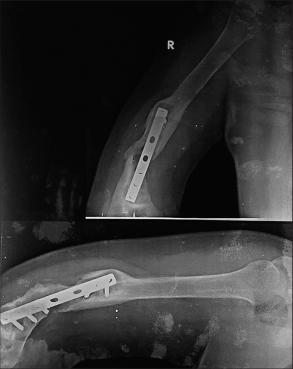
- Anterior posterior and lateral radiographs of the right humerus showing nonunion with hypertrophic callus formation. Note the peri-implant lucency is more than 2 mm thick indicating hardware loosening.
Atrophic non-union
It may be seen in devitalized bone and may be iatrogenic or secondary to soft-tissue injury during the trauma. Due to the lack of blood supply, the fracture ends are osteoporotic and atrophic which are radiographically identified as absent callus formation. Non-weight bearing results in the bone ends being radiographically dense compared to the adjacent viable bone which appears more osteopenic. In radionuclide studies, such fracture sites are “cold” with no uptake. These are commonly seen in tibial fractures treated with plates and screws [Figure 2].[1,5,7]
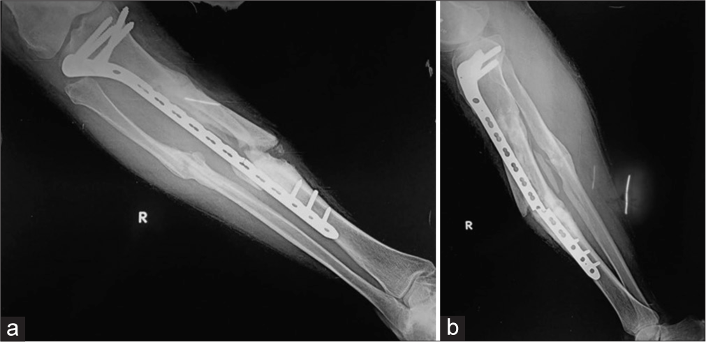
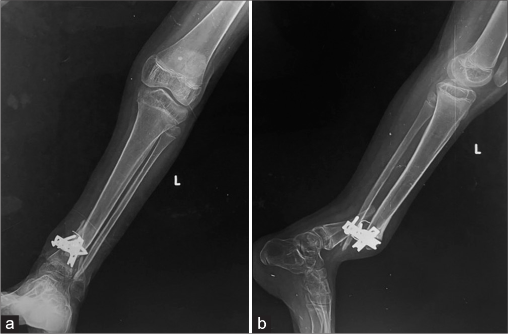
- (a) Anterior posterior (AP) and (b) lateral radiograph of the leg showing buttress plate with fixation screws proximally for fracture mid shaft of the tibia, showing atrophic non-union, due to rigid fixation and distraction at the fracture site. Also note implant failure was identified clearly on lateral view only, seen as a faint fracture only on the AP view. It is seen at the screw hole, which is the weakest point in a plate. The soft-tissue density with linear opacity identified on the lateral view is artefactual.
Oligotrophic non-union
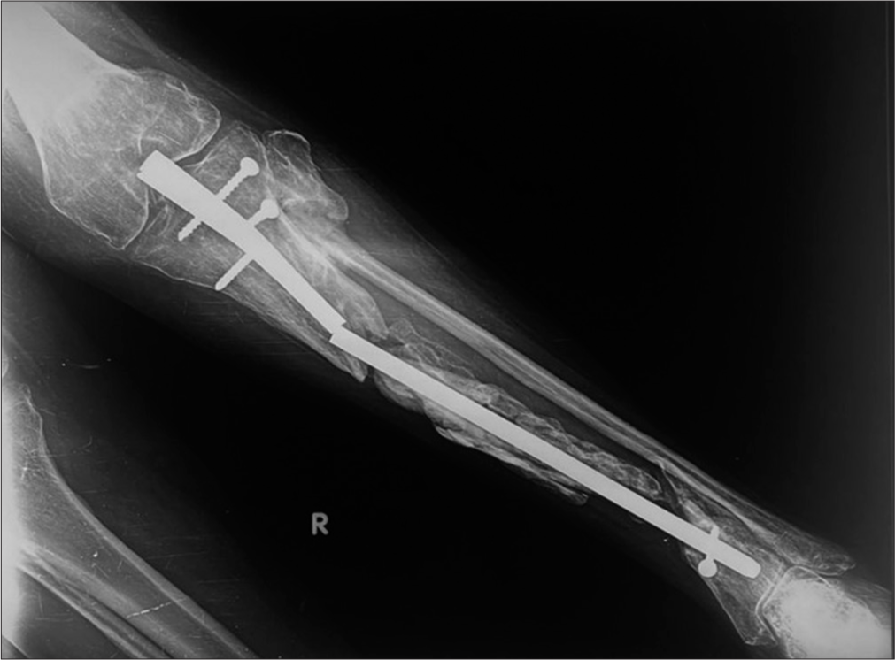
There is insufficient callus to bridge the fracture site which suggests adequate vascularity and is often seen secondary to inadequate apposition of fracture fragments, for example too large a gap. As the bone is viable, but lacks stimulus, there is resorption of the fracture ends. This is often seen after major displacement of fractures, the distraction of fragments, or inadequate apposition of fragments. There is radio-isotope uptake on radionuclide scans of this type of non-union. The implants may weaken or break secondary to increased load bearing, causing motion at the site with stimulation of the healing process [Figure 3].[1,5,7] Non-union can lead to other complications as well, for example, Scaphoid Non-union Advanced Collapse with ununited scaphoid fractures.
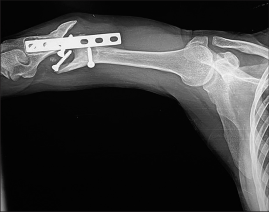
- Lateral radiograph of the humerus showing oligotrophic non-union with displaced and migrated screws and plate.
Septic non-union
Due to infection, the nutrition to the bone is utilized by the infecting organism, reducing the blood supply, and thereby decreasing new bone formation. However, sometimes, abundant callus can be also visualized [Figure 4]. This will be discussed in detail later in the article.
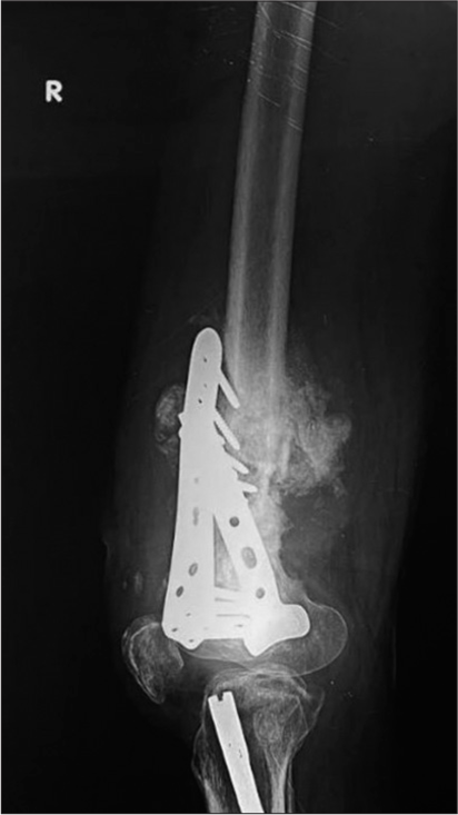
- Lateral radiograph of the femur with distal buttress plates and screws showing hypertrophic callus with surrounding soft-tissue densities suggesting infection. An intramedullary nail is also seen in the proximal tibia with surrounding lucency suggestive of loosening.
UNDERSTANDING FAILURE OF FRACTURE FIXATION
Implants used in the fixation of fractures are meant to maintain the alignment and length while keeping them in position and allowing the healing process to take place. Most implants are bioneutral and can be left within. Removal is now optional in adults, but they are always removed in pediatric patients. However, these implants have a finite life when the adjacent bone is weak. If the healing is completed within 3–6 months, the bone becomes strong enough to take over the implant. But, in delayed or non-union, the implant continues to bear the load, reaching its fatigue threshold, leading to loosening or failure. Similarly, implants positioned at places with natural motion after healing, like joints, can experience a delayed failure. Hardware can also fail if the load placed on it exceeds its ability to resist that load. This may be seen when patients are non-compliant and start early weight bearing or when the construct is weak, for example, poor bone quality or poor implant application or design. Screws wrongly placed within the fracture line are also an example of when implants can lead to delayed/non-union.[1]
IDENTIFYING DEVICE FAILURE
As already stated, complications common to all devices include loosening, fracture, and migration.
Loosening is identified as a progressive periprosthetic lucency or “halo” of more than 2 mm. Hence, stating the importance of comparative studies. Progressing lucencies may indicate a failing implant, unstable fixation, or sometimes infection [Figures 4 and 5].
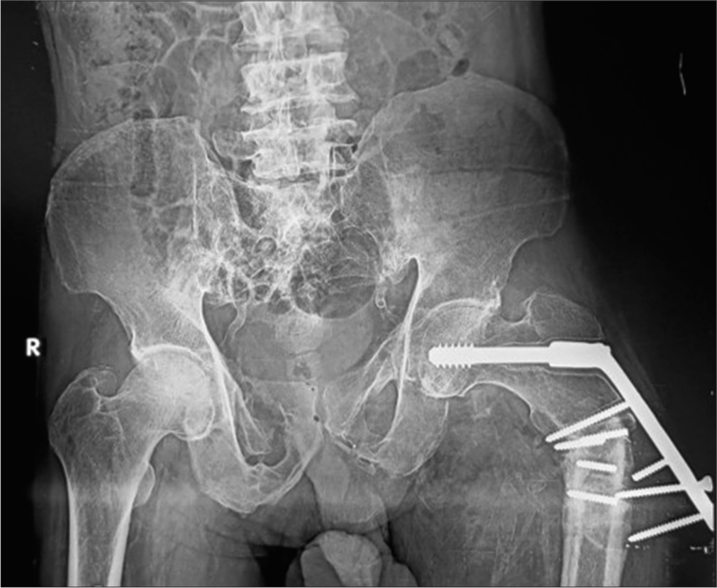
- Anterior posterior radiograph of the pelvis showing dynamic hip screw (DHS) in situ. Varus deformity of the hip is seen with classical periprosthetic lucency more than 2 mm wide, displaced plate, loosening, and fracture of the screws. This suggests that the patient continued to walk on the varus hip forcing the DHS to come out leading to failure. Also, note background osteoporosis.
Screws can be used individually to join two parts of the fractured bone or together with a plate or suture or intramedullary (IM) nail (where they are known as bolts) to attach them to the bone. Complications common to screws are loosening or breaking. Loosening, as already mentioned, is seen as a halo around the implant or where the interface is compromised. Slowly, the screw may begin to back out and migrate as it loosens [Figure 6]. Careful examination of the contact of the screw with the adjacent bone and comparison with previous radiographs may reveal subtle changes in the position. Bolts used in interlocking nails together with IM nails troughing through the weak metaphyseal bone are an example of this.[1]
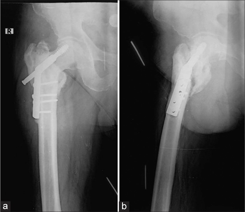
- (a) Anterior posterior and (b) Lateral radiographs of the right hip with intertrochanteric fracture status post-dynamic hip screw (DHS) showing superiorly displaced/cut through and backed out DHS screw. Note the prominent periprosthetic lucencies around the screw in the head on the lateral view only and the associated non-union.
Constant motion or abnormal weight bearing may also cause the screws to bend, break, or loosen out. This is often seen when screws are placed near a joint or secondary to abnormal weight bearing leading to a stress-related fracture of the hardware [Figures 5 and 7].
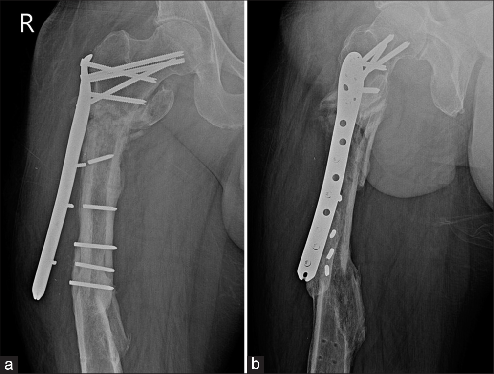
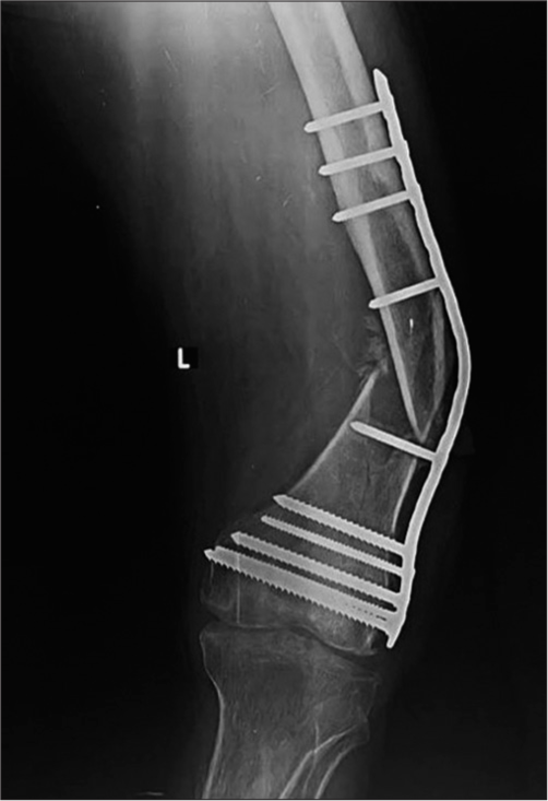
- (a) Anterior posterior and (b) Lateral radiographs of the right thigh showing plate and screw failure secondary to nonunion of subtrochanteric fracture with loss of contact of the compression plate from the shaft. Old, healed, fracture shaft of the femur is seen with tracks from previous implants.
When used in conjunction with a plate, screws can fail near the bone or plate interface as they are the weaker structure. One should also not forget that the placement of any device, especially a screw means that a hole has to be drilled into the bone, causing weakening of bone. Furthermore, as a result of “stress shielding,” the adjacent bone may weaken, creating a vicious cycle.
Bioabsorbable screws are radiolucent and hence, it is the width of the track that must be followed. Any asymmetrical widening or loss of parallelism is indicative of loosening [Figure 8].[8]
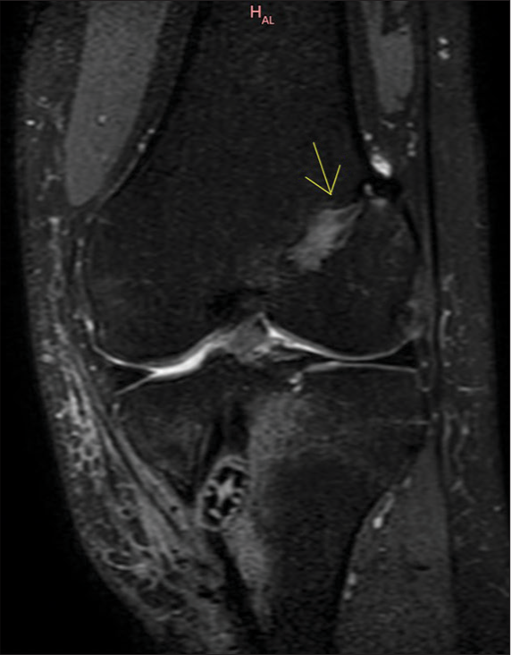
- 29 years male. Status post double bundle anterior cruciate ligament repair. The patient presented with discharging sinus in the proximal leg. A coronal proton density fat saturated (PDFS) image of the left knee shows a widened femoral track with the interference screw in the tibial track (yellow arrow). Adjacent altered marrow and soft tissue signal intensities suggest edema along the bio-absorbable screw.
In plate fixation, loss of lucency at the fracture line is suggestive of good healing. However, any widening at the fracture ends or fracture of the plate is suggestive of instability.[9]
Both nails and plates can also fail by bending or breaking. This is most often seen around areas of high strain concentration, such as a non-union, poor stability/early mobilization, or trauma leading to persistent or refracture [Figures 9 and 10].
- Anterior posterior radiograph of the femur showing a bent plate. During the initial phase of mobilization, the plates bear the load. Once the fracture gets “sticky” the bone starts to “share” the load. In the absence of a callus, the entire weight is taken by the plate, as seen in this case, leading to eventual failure.
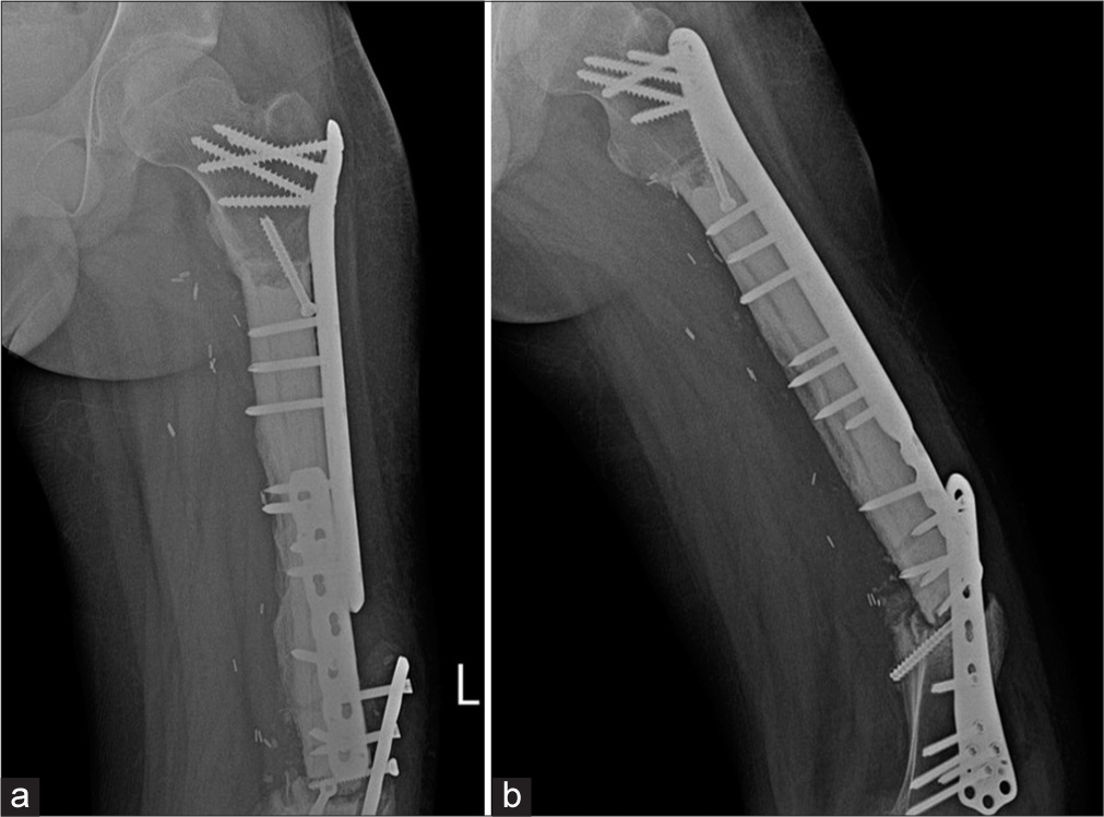
- (a) Anterior posterior and (b) Lateral radiographs of the left thigh. Patient was a known case of Ewings sarcoma with surgical excision, cement placement. Buttressing and compression plates are seen in situ with loosening of the plates and screws on the background of a non-united fracture. Patient did not follow directions and mobilized early. The patient was operated upon again and was asymptomatic on follow up.
Plate fractures usually occur at the screw hole, which is the weakest point [Figures 2 and 11]. Studies also show the lag screw to be the weakest spot.[10] It is worthwhile recalling that a lag screw is an interfragmentary screw that is used to compress fracture fragments.[11] This may be a subtle finding, therefore one must look for a step off in the contour. Plate fractures may be identified only on one view, especially if they are parallel in orientation. Hence, it is important to assess the plate in two orthogonal views.
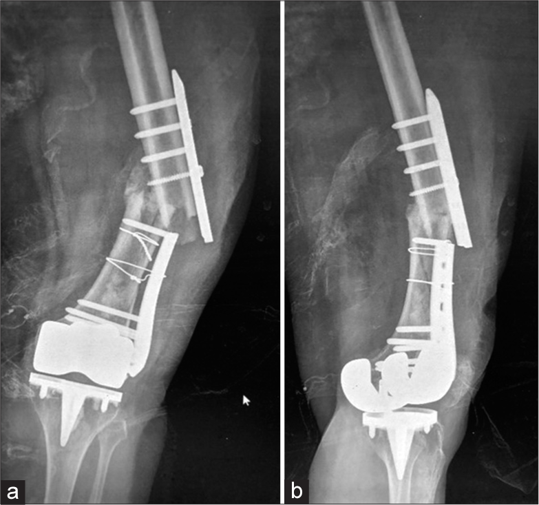
- (a) Anterior posterior and (b) Lateral radiographs of the left thigh with knee. Morbidly obese patient, status post Total Knee Replacement (TKR) and diaphyseal fracture of the femur. Patient had a fall. Radiographs show intact knee prosthesis with a broken compression plate and refracture. See the beveled edges at the site of plate fracture, suggesting break at the screw hole.
IM nails can cross into the joint space, damaging the internal cortical blood supply, and increasing the likelihood of secondary infection [Figures 12 and 13].[9]
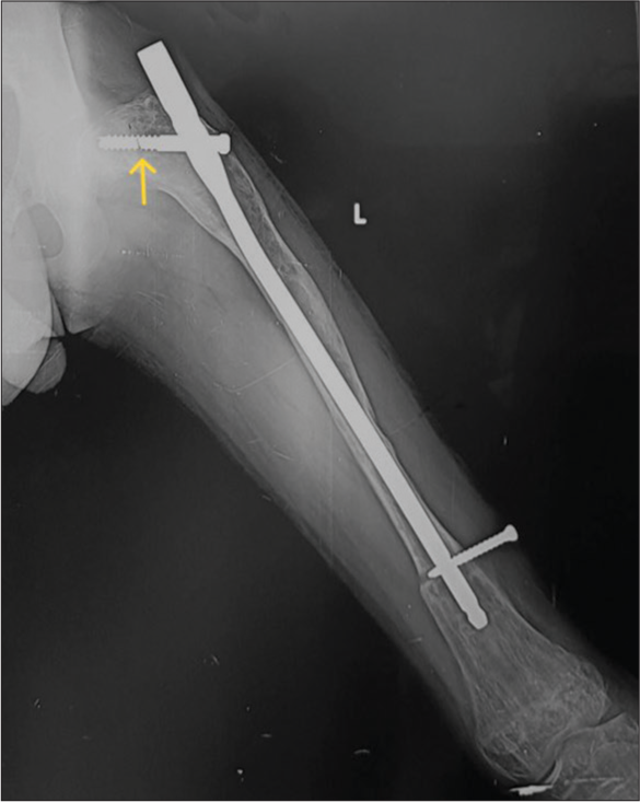
- Anterior posterior radiograph of the left femur showing improper position of intramedullary nail-It is “proudly” (too proximal and outside the bone) placed with poor working length. Also, note the discontinuity in the proximal screw (yellow arrow) while the distal screw has backed out.
- Anterior posterior radiograph of the leg with improperly positioned intramedullary (IM) nail with proximal end seen in the knee joint. There is non-union with sequestrum suggesting sequelae of infection. There is failure of the implant with fracture of the IM nail and proximal bolts.
It is important to evaluate the immediate post-operative radiographs to assess any subsequent subtle changes in the position of the implants. Screw displacement is such an example, as they may migrate from their original position. Cannulated screws used to fix fracture neck of femur fractures may migrate within the neck or medially, crossing the joint space and compromising the blood supply leading to avascular necrosis (AVN) or causing acetabular damage with resultant secondary degenerative changes [Figure 14].
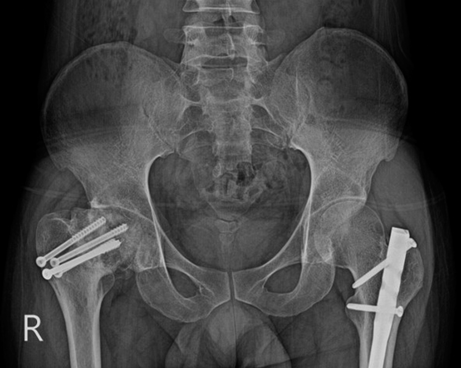
- Anterior posterior radiograph of the pelvis. The patient was operated on for a fractured neck of the right femur with cannulated screws. The head is now collapsed with the loss of definition, consistent with avascular necrosis, which is a known complication. The radiologist needs to be aware of this complication and should look for it. Note is made of an intramedullary nail in the left femur, placed for femoral shaft fracture.
Dynamic hip screws used in intertrochanteric fractures are also subject to loosening, migration, and fracture. There is also a minimal risk of compromised cortical blood supply secondary to the large surface area in contact with the cortex, risking delayed, or non-union [Figure 15].[9]
- AP Radiograph of the pelvis with backed out dynamic hip screw. Note how the screw is displaced superiorly in the head of the femur.
There is a concern for pressure-induced bone necrosis and cerclage wires should be placed at least 1 cm away from a fracture fragment. They should also not to be used in the presence of butterfly or comminuted fractures.[2,12]
An implant may also fail if the appropriate hardware is not used or the placement uses poor technique [Figures 16-18].
- (a) Anterior posterior and (b) lateral radiographs of the leg showing fractures of the distal tibia and fibula, demonstrating poor fixation with only 2 screws on either side, leading to implant failure, from poor choice of the implant.
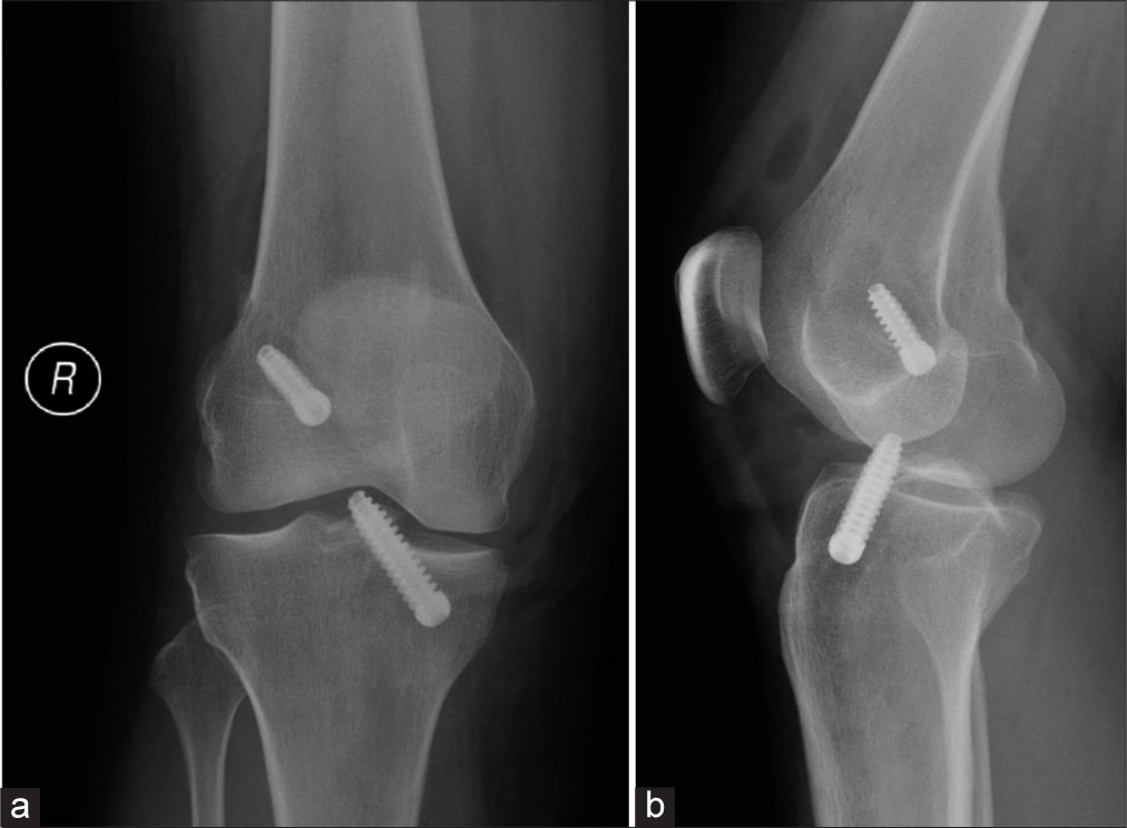
- (a) Anterior posterior and (b) lateral knee radiographs taken immediately post-op (note the intra articular air) after anterior cruciate ligament reconstruction show unusually prominent tibial screw abutting the trochlear groove of the femur. (Image Courtesy Dr Raj Chari, Consultant Musculoskeletal Radiologist, Oxford University Hospitals NHS Trust).
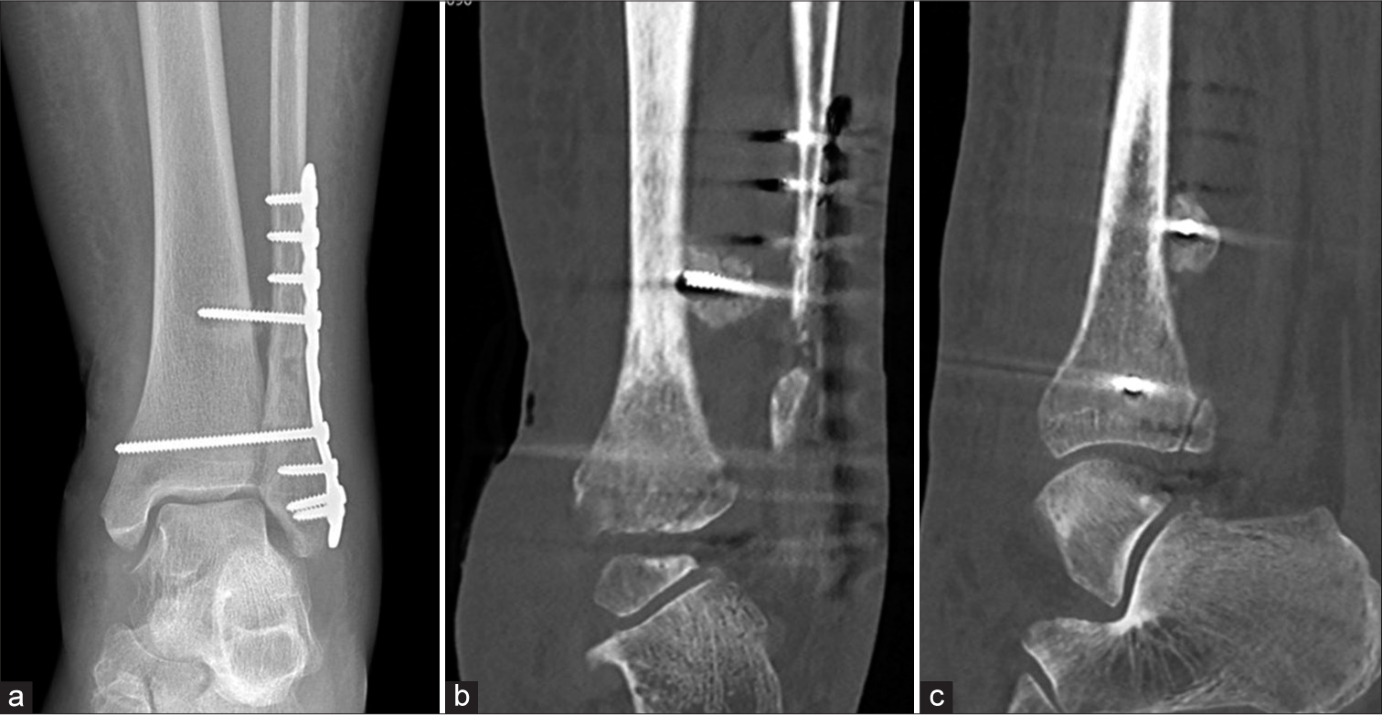
- A 25-year-old man with increasing ankle pain following open reduction and internal fixation. (a) Anterior posterior radiograph of the ankle showing subtle lucency at the tip of the proximal tibia-fibula screw. It is unlikely to represent prosthetic loosening as the syndesmotic screw does not show other signs of loosening. (b) Coronal and (c) sagittal CT reformatted images show that the screw tip is situated posterior to tibia instead of within the tibia. Note significant callus formation around the screw tip. (Image Courtesy Dr Raj Chari, Consultant Musculoskeletal Radiologist, Oxford University Hospitals NHS Trust).
SEPTIC VERSUS ASEPTIC LOOSENING
Peri-implant infections are a dreaded complication and are often difficult to diagnose in the initial stages. With an average incidence of 5% ranging from 1% to 2% in closed fractures, they can be as high as 30% in open fracture reductions.[13,14]
These infections can be acute (occurring within 2 months), subacute (3–24 months), or chronic (more than 2 years) post-surgery.[14] The combination of history, clinical examination, laboratory, and radiological findings help the diagnosis.
Periprosthetic bony abnormalities suggesting infection are [Figures 13, 19, and 20]: [14]
Bone sequestrum
Periprosthetic lucency increasing more than 2 mm/year
Rapid alteration of the adjacent bone, especially the areas outside the stress
Blurring of the edges of periprosthetic margins with multifocal areas of osteolysis
The periosteal reaction may be extensive, poorly circumscribed or solid, thin, or not adherent to the cortex
Gas surrounding the implant
Bipolar loosening.
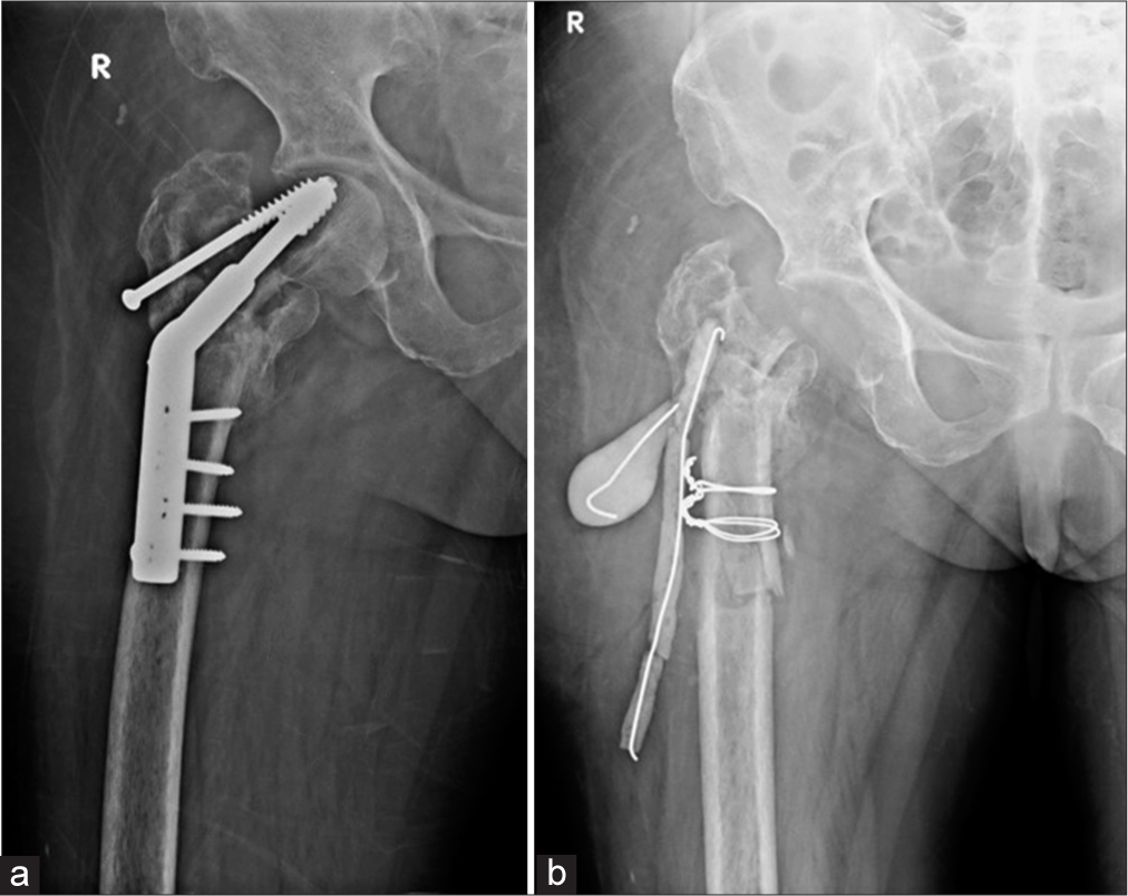
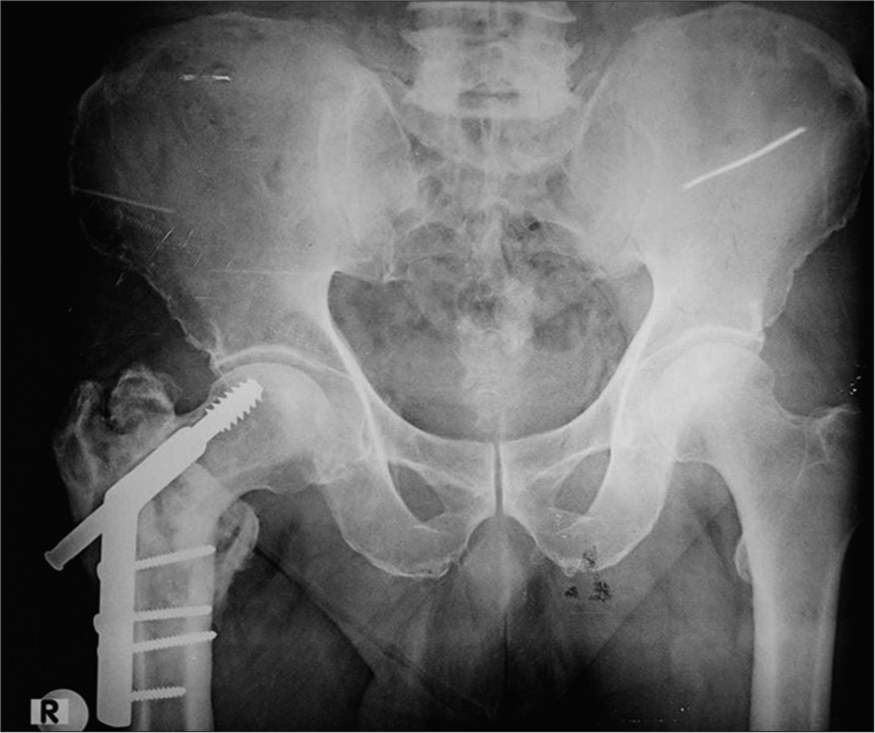
- (a) Anterior posterior (AP) radiograph of the right hip show displaced dynamic hip screw with irregular lytic areas in the greater trochanter suspicious for infection. (b) AP view of the right hip, status post-surgical removal of the femoral head with placement of antibiotic laden K wires and cement. Cerclage wires were also placed for intra operative fracture of the shaft.
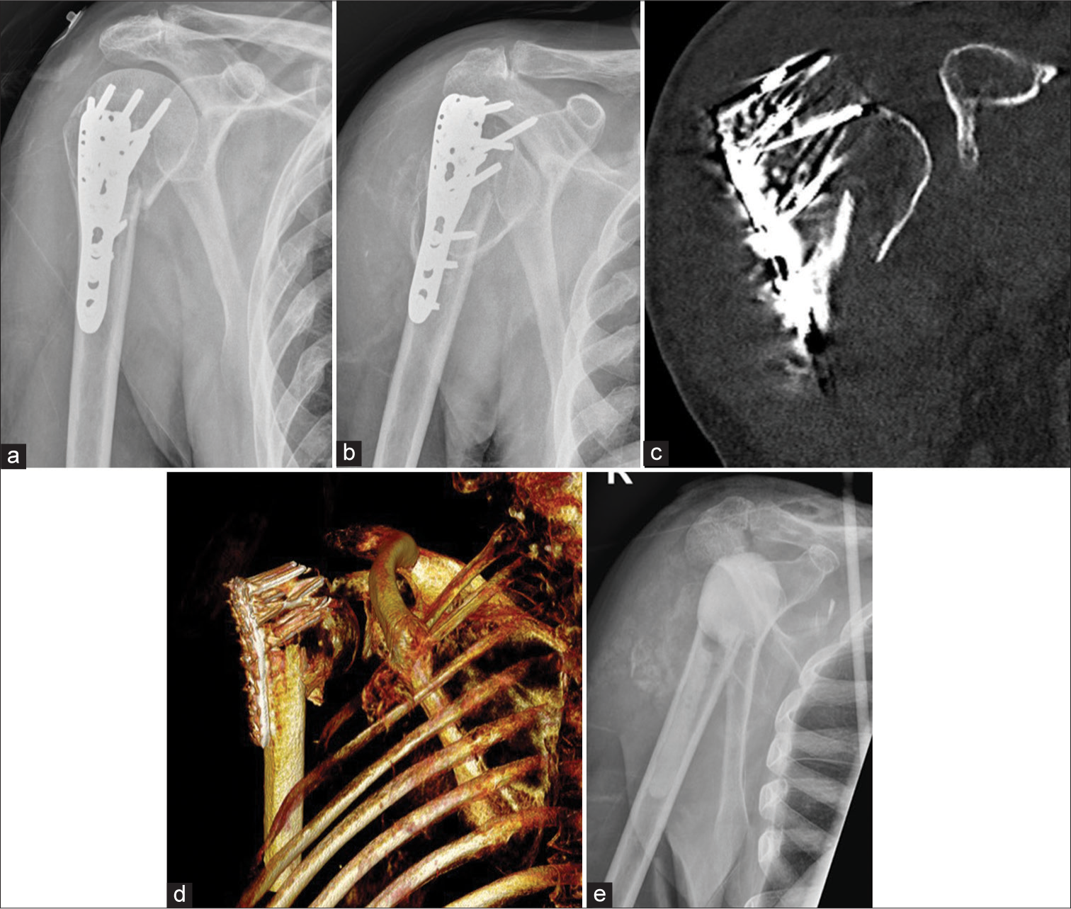
- Anterior posterior radiographs of right shoulder taken 3 weeks apart (a) initial radiograph, (b) taken 3 weeks later, showing rapid destruction of the humeral head with exposed screws of the humeral internal fixation. Also note the multiple, old, rib fractures. (c and d), coronal and volume rendered CT images show exposed metal work and attenuation of the humeral head. (e) Post-operative Y view showing removal of metalwork and cement placement as a part of two stage replacement. (Image Courtesy Dr Raj Chari, Consultant Musculoskeletal Radiologist, Oxford University Hospitals NHS Trust).
Periprosthetic soft-tissue changes suggestive of infection are [Figure 21]: [14]
Soft-tissue collections
Edema
Sinus tracts
Joint distension.
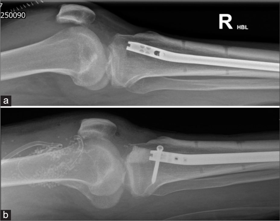
- A 34-year-old man with a recent intramedullary nail fixation for a tibial fracture became acutely unwell within a week of his Surgery. (a) lateral knee radiograph on the 7th day shows large knee joint effusion which on aspiration grew Gram +ve cocci. (b) Lateral knee radiograph showing exchange of intramedullary nail, bone cement, intra articular antibiotic beads and surgical drain. (Image Courtesy Dr Raj Chari, Consultant Musculoskeletal Radiologist, Oxford University Hospitals NHS Trust).
While there is no gold standard, conventional radiology still forms the backbone of imaging/detecting periprosthetic infections. Despite having a sensitivity of 14% and specificity of 70%, 50% of plain radiographs appear normal in the presence of infection. However, they remain the first line of imaging and serve as a reference to monitor the progression of the disease.[14,15] Serial plain radiographs play a critical role in identifying subtle peri-implant changes such as migration or early loosening, helping differentiate from infection [Figure 22].[16]
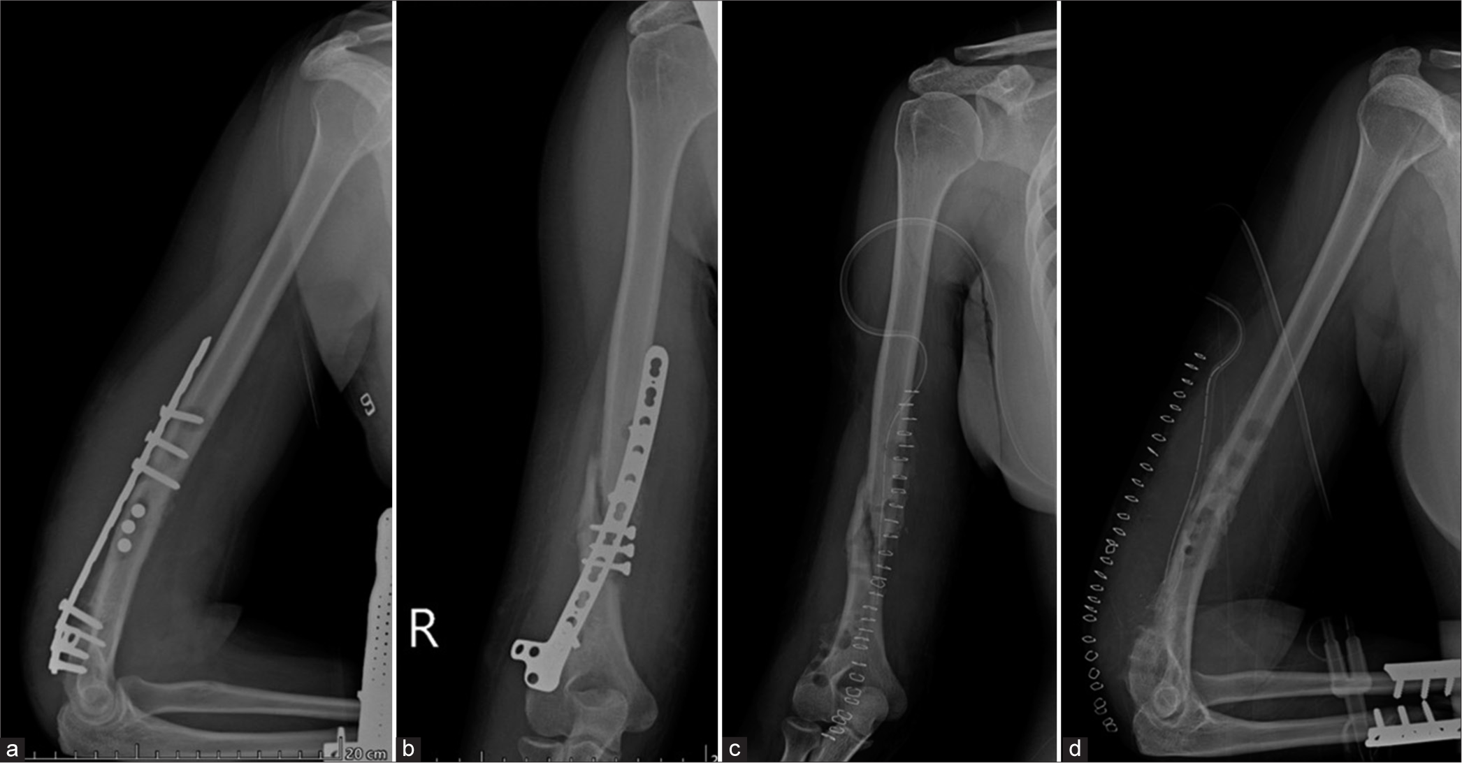
- (a) Anterior posterior (AP) and (b) lateral views of the humerus. On the AP view, sclerotic fracture margins are seen suggesting oligotrophic nonunion, which is not identified on the lateral view. Alignment of bone is maintained. There is a loss of alignment of the compression plate on the AP view with a loss of contact distally, as seen on the lateral view. Well-defined lucencies are also seen around the proximal screws, indicating mechanical loosening. (c) AP and (d) lateral views of the humerus show surgical removal of the implant with the drain in situ. Also, note the compression plates for radial and fibular fractures on the lateral view.
With the advent of newer protocols reducing the metallic artifacts from the hardware, computed tomography (CT) provides greater details and is especially useful in anatomical sites difficult to visualize on conventional radiographs. The added advantage is also the visualization of the soft tissues for any associated abnormalities which along with IV contrast can make the diagnosis of an infection/abscess easier. Dual-energy CT (DECT), though not routinely used as yet, has shown promising results in reducing metallic artifacts from the hardware and, aiding in detecting periprosthetic fractures, by demonstrating the bone marrow edema at these sites.
Ultrasound (USG), not affected by metal artifacts, can be utilized to identify soft tissue abnormalities such as periprosthetic infections/abscesses and aseptic lymphocytic vasculitis-associated lesions (ALVAL) and may be used to guide aspiration of infection and biopsies.[16]
Magnetic resonance imaging (MRI) with newer metallic artifact reduction sequences (MARS) can be utilized to image hardware-related complications when there is clinical suspicion of infection that is not evident on plain radiographs or CT. Bone marrow edema and soft-tissue edema are identified as hyperintensities on T2-weighted/Fluid restricted sequences helping the radiologist arrive at the diagnosis. Enhancing collections or sinus tracks can be identified post-IV gadolinium contrast and non-enhancing, central universally hypointense foci, suggestive of sequestrum can also be detected.[14]
99mTc labeled bone scintigraphy is another modality that is often used to diagnose periprosthetic infection. Increased uptake in the triple phase scan suggestive of hyperemia, increased tissue diffusion and increased tracer uptake in the late phase is predictive of infection. While the sensitivity is high, the specificity is low, resulting in poor differentiation between infection and mechanical loosening.[14] This modality is thus not used frequently.
UNCOMMON PERI-IMPLANT COMPLICATIONS
Uncommon implant-related complications include pseudoaneurysms, bursitis, muscle impingement with atrophy, adverse reaction to metal debris (ARMD), nerve impingements, traumatic neuroma formation, tendon impingement and snapping, and lastly sarcoma [Figure 23].
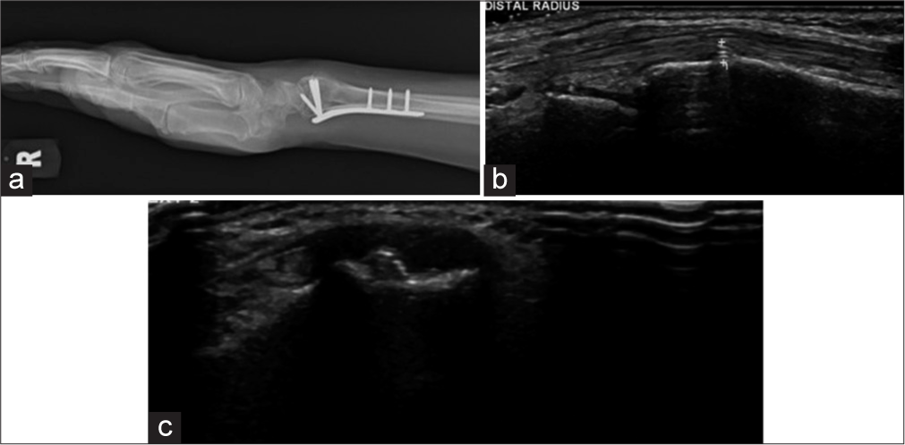
- (a) Lateral radiograph of wrist showing plate and screw fixation. The distal row of screws was not seen to breach the cortex in the radiograph. (b and c) Longitudinal and transverse ultrasound images show a prominent screw tip adjacent to the Lister tubercle causing second extensor compartment tendinosis. (Image Courtesy Dr Raj Chari, Consultant Musculoskeletal Radiologist, Oxford University Hospitals NHS Trust).
Pseudoaneurysms may develop due to indirect trauma during the surgery or secondary to repetitive irritation by hardware or bone fragments. They may present with pain, pulsatile mass, or bleeding. USG can help confirm the diagnosis. CT or MR angiography may further delineate the offending artery.
Muscle and nerve impingements and snapping syndromes also have similar etiologies and are present with characteristic history. Snapping syndromes can be beautifully elicited by dynamic USG. Muscle and nerve impingements may lead to atrophy of the respective muscle which can be visualized by reduced bulk and fatty replacement on CT and MRI.
Traumatic neuromas may be classified as terminal (TN)/ end bulb neuromas or neuromas in continuity (NIC) and can simulate peripheral nerve sheath neuromas on imaging. Injury to the peripheral nerve sheath may occur during trauma or can be iatrogenic during surgery by internal or external fixation or during amputation. This results in failed regeneration and multidirectional cell proliferation with loss of normal nerve architecture. As the name suggests, NIC is seen after partial resection, maintaining continuity with the parent nerve proximally and distally, exhibiting a “tail sign,” while TN has no distal continuity. On MRI, they are isointense on T1-weighted images and heterogeneously hyperintense on fluid-sensitive sequences. A capsule may or may not be identified. Post-contrast enhancement may be seen rarely. The differential diagnosis is peripheral nerve sheath tumor (PNST) which lacks the characteristic history of trauma. However, on MRI, the lack of a “target sign” which is seen in PNST, likely representing central fibro collagenous tissue surrounded by a peripheral rim of hyperintense myxomatous tissue, is suggestive of the traumatic neuroma. Furthermore, PNSTs are not usually associated with skeletal muscle denervation, unlike traumatic neuromas.[17] On USG, these are easy to evaluate, especially if situated in the extremities, and can be identified as a hypoechoic lesion at the site of pain or along the nerve with loss of normal fascicular pattern. They may be encapsulated and generally have a diameter greater than the parent nerve.[18]
ARMD or metallosis have been more commonly described post arthroplasties and are uncommon post-open reduction and internal fixation (ORIF). Most patients present with debilitating pain and soft-tissue masses with an insidious onset. Biochemical markers can help it to differentiate from infections. Radiological signs described are “metal line sign” which is a radio-opacity due to metallic debris and “bubble sign” which is metallic debris outlining the joint surface.[19] However, in ORIF as no joints are involved, these signs may not be visualized. Bony osteolysis and periosteal reaction have been described on radiographs in extremities.[20] The associated soft-tissue pseudotumor is hypointense on T1-weighted and hyperintense on T2-weighted sequences with hypointense septations. Foci of blooming may also be identified on Gradient Echo Sequences (GRE) sequences along with minimal peripheral enhancement post-contrast.[21]
AVN requires special mention as an uncommon, but not unknown complication of surgical management of femoral neck fractures. As the findings may be delayed on conventional radiographs, a patient presenting with pain should be considered with a high index of clinical suspicion warranting an MRI [Figure 14].
Implant-associated malignancies are very rare complications. A literature search by Keel et al. reported 31 sarcomas (with osteosarcoma being the most common subset) and two implant-associated lymphomas.[22,23] These often present as slow-growing soft-tissue swellings with pain. Histopathological examination is necessary to make a final diagnosis as radiological findings may be non-specific.
RADIOLOGICAL EVALUATION
As stated in part 1 of this article, the radiologists need to consider few technical requirements for imaging these surgical devices/implants as outlined:
Conventional radiology is the imaging modality of choice
A minimum of two orthogonal views are mandatory. This is especially important when the failure plane is parallel to the radiographic plane
The radiographs should cover both joints above and below the implants or at least one joint closest to the fracture
The entire length of the implant should be identified and include some of the normal bone proximal and distal to the hardware/fracture site
With computed radiography and digital radiography systems, image manipulation can be easily performed and 3D CT images can be obtained without difficulty. Metal artifact reduction techniques/software need to be utilized to prevent/reduce artifacts in both CT and MRI
As several findings may be subtle, comparison with the previous imaging is MANDATORY. Ideally, pre-operative, immediate postoperative, and all follow-up serial plain radiographs must be reviewed to evaluate for interval change.
SUGGESTED CHECKLIST
As we are aware of what we need to look for while evaluating plain radiographs of various hardware, let us review some tips for identifying hardware failure and complications.
Tips for plain radiographic evaluation of osseous hardware.
-
Evaluate the clinical aspects
Where and what was the primary fracture?
What surgery was undertaken?
Has realignment of anatomy been obtained to a reasonable extent?
-
Evaluate the technical aspects
Identify the type of fixation
Identify the implant
-
Check for the integrity of the adjacent bone
Look for delayed union or nonunion, which if present, may increase the load on the implant resulting in failure.
Check the alignment of the device – improper alignment can lead to failure
Check for the position of the device – ideally, compare with previous radiographs to see any change in position. In the immediate postoperative period the device should be in the expected position.
Check the integrity of the device – search the entire length of the hardware to identify any discontinuity.
As already stated, it is ideal to compare with previous serial plain radiographs, especially immediate post-operative ones, so that the radiologist can identify an impending failure early on.
ROLE OF OTHER IMAGING MODALITIES
USG
It is a good imaging modality to examine the peri-implant soft tissues to identify collections or solid lesions like ALVAL. It can also be used to perform US-guided procedures for biopsies or aspirations [Figure 23].
CT
The immediate post-operative imaging modality of choice remains plain radiography. However, with improvement in the metal artifact reduction techniques, CT is now being more commonly used for the evaluation of fracture healing and hardware-associated complications [Figures 18, 20, 24-28]. The radiologists should familiarize themselves with the common indications for postoperative CT, the various protocols, and techniques to optimize the study.[24]
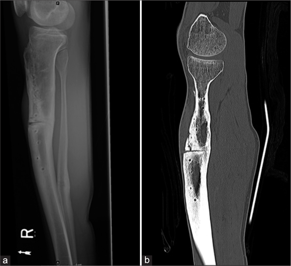
- (a) Lateral radiograph of the leg shows non-union in the mid-shaft of the tibia with screw tracks from removed implants. An osteotomy was performed for the non-union. Also noted healed fracture of the distal shaft of the fibula. (b) Sagittal CT reformatted image shows a vertical fracture from the osteotomy which was not seen on the radiograph.
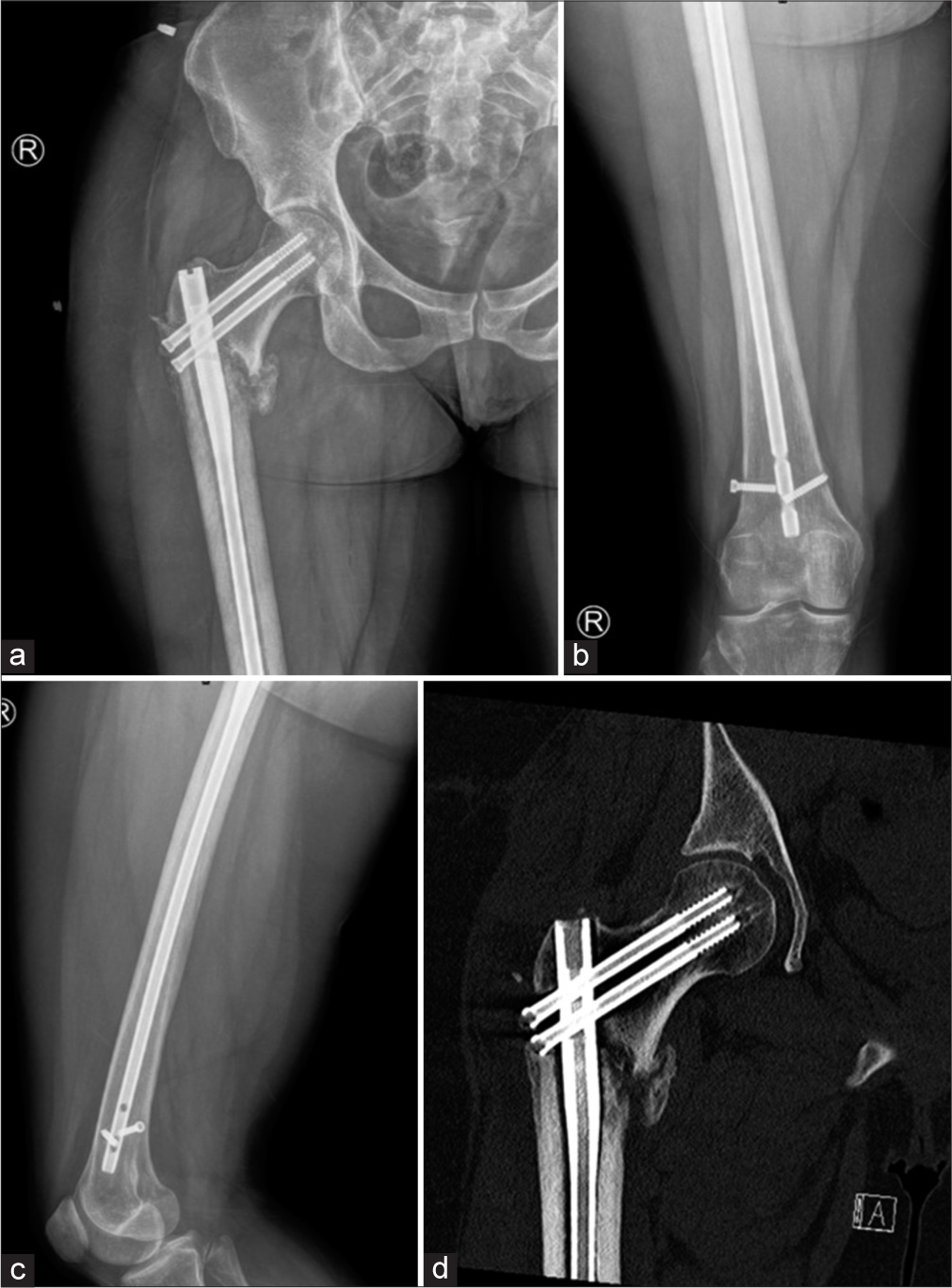
- (a) Anterior posterior (AP) view of the right hip (b) AP view of the right thigh and (c) lateral view of the thigh shows lucency in the subtrochanteric region of the lateral femur from early loosening. Distal intramedullary rod- interlocking screw is broken with loosening. Also, the head of the distal of the two proximal screws is located within the fracture as shown in CT (d). Early loosening at the lateral subtrochanteric femur is confirmed on CT.
- Sagittal CT reformatted radiographs of the tibia show a dynamic compression plate with backed out 3rd and 4th (counting from proximal) screws.
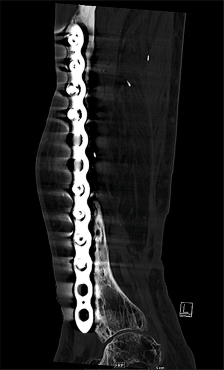
- (a) Anterior posterior (AP) radiograph of the leg showing tibial and fibular fractures dynamic compression plate and vascularized graft. Note that screw fracture was identified on both the radiograph and CT (b). The position of the screws is better seen within the new bone on CT due to reformats.
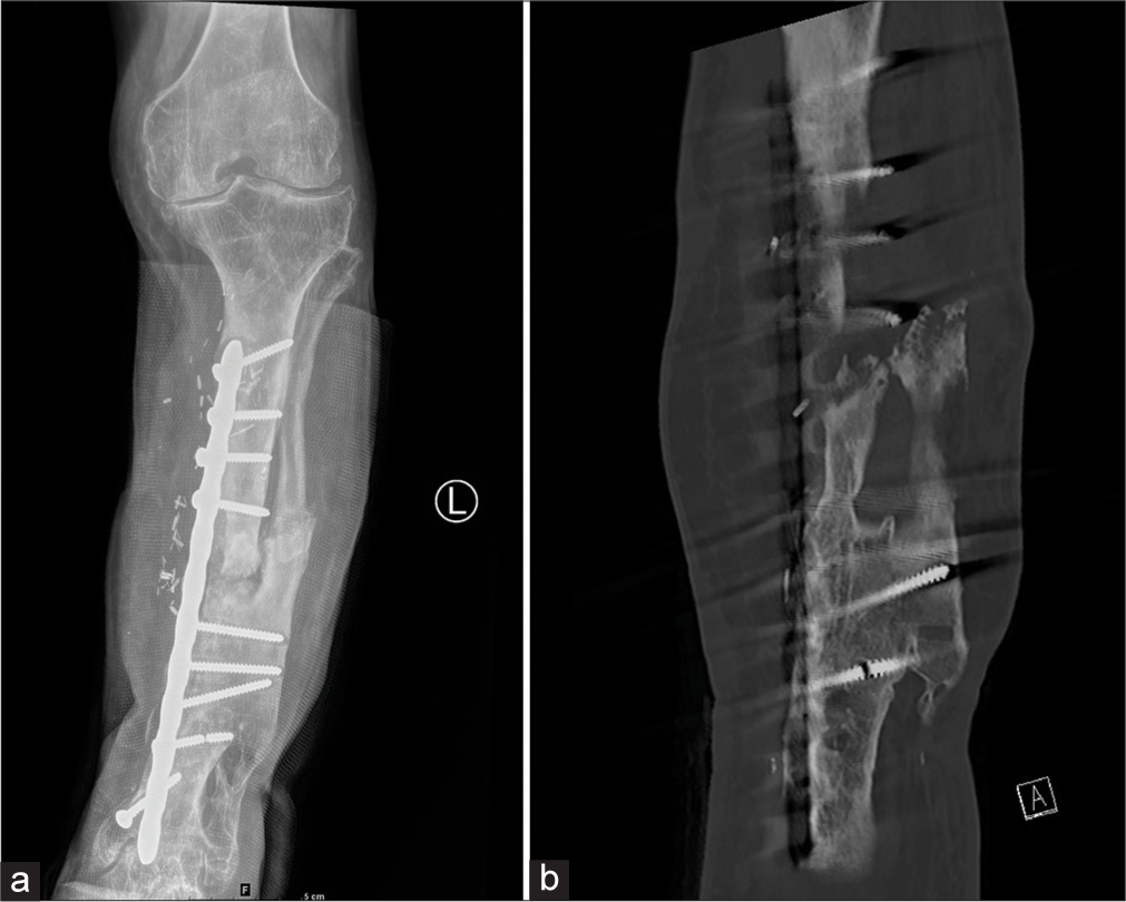
- (a) Anterior posterior (AP) radiograph of the leg with (b) CT coronal and (c) 3D reformations with vascularized graft show break in the dynamic compression plate, proximal to the 5th screw (counted cephalic to caudal); Confirmed on CT reformats but sometimes as in this case, plain radiographs demonstrate hardware failure better. So always compare with plain radiographs.
In the immediate postoperative period, CT may be used to evaluate post-hardware placement, (such as an external fixator), reduction of an intra-articular fracture, or before planning revision surgery.
CT may also be used to evaluate periprosthetic fractures which may be acute or chronic. Stress fractures can also be evaluated and are more often chronic. CT is also useful to evaluate osseous bridging in non-union, where it has been shown to be more accurate compared to plain radiographs.[25]
Periprosthetic loosening can also be evaluated on CT, as described, to differentiate septic versus aseptic loosening.
Recent studies in the literature have shown that DECT can be used as an additional option for the reduction of metal artifacts. This modality has been useful in reducing beam hardening artifacts as they use monoenergetic X-ray beams compared to poly energetic X-ray beams in conventional CT. These virtual monoenergetic images (> 70 keV) have been shown to increase the identification of prosthetic and periprosthetic tissues in several metallic hardware without an increase in the dose of radiation.[26,27] The prosthesis composition and size also thus, play an important role in artifact reduction. Materials such as cobalt chrome cause artifacts mainly due to photon starvation, compared to less dense materials like titanium where beam hardening is the main factor.[28] DECT can also be used in metallosis for the detection of metal debris and pseudotumors.[26] DECT is, however, not routinely used but will become increasingly popular globally, as more institutions acquire the instrumentation/software.
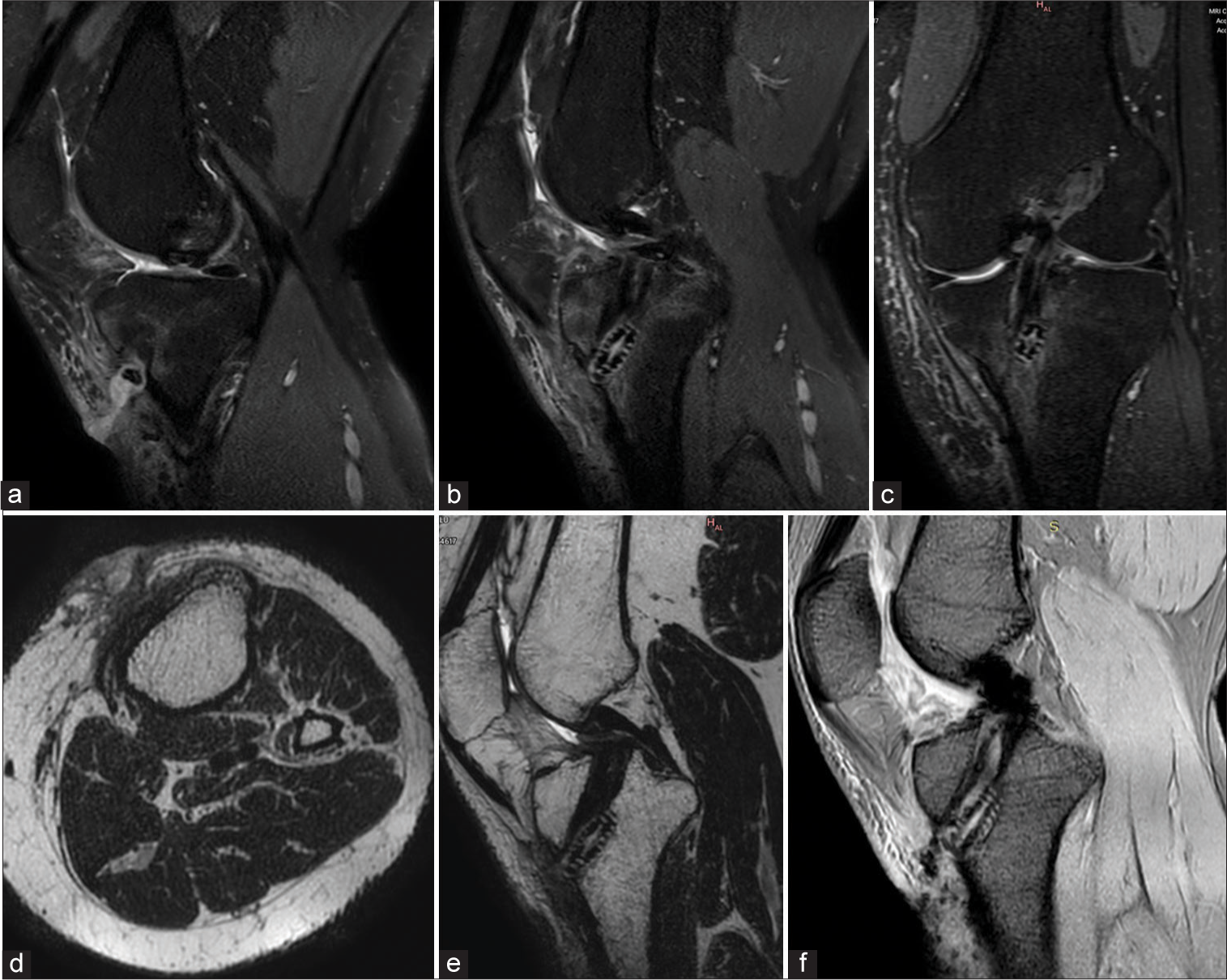
- Same Patient as Image 8. Status post-double bundle anterior cruciate ligament repair. The patient presented with discharging sinus in the proximal leg. (a) Proton density fat-saturated sequence extreme sagittal and (b) midsagittal images show a hyperintense track in the soft tissues anterior to the tibia extending up to the dermis with marrow edema in the tibia. Soft-tissue edema is also seen in the soft tissues anteriorly and medially (c) on the coronal images. (d) Axial T2W image at the level of the tibia showing the track in the subcutaneous planes breaches the skin. (e) Corresponding Midsagittal T2W image. (f) Gradient echo sequences mid sagittal image showing foci of blooming in the intercondylar region and pretibial soft tissues.
MRI
MRI provides a better evaluation of the soft tissues, especially when assessing pseudotumors in metallosis, soft-tissue, marrow edema in infective etiology, and other soft-tissue lesions. The newer MARS sequences have increased the possibility of MRI applications.[24] However, this modality is not generally used in routine practice with metallic implants. Foci of blooming are often seen along the tracks of the scope and at the hardware site. It is, however, frequently used to evaluate postoperative anterior cruciate ligament repair complications [Figure 29].
CONCLUSION
With the increasing number of options for surgical management of fractures available, it is now imperative that radiologists familiarize themselves with various hardware used to be able to provide a good support system for the treating surgeons.
The common complications one can expect to see in daily practice include hardware loosening, fracture, and migration. As radiologists, we can also use the various modalities described in this article to differentiate aseptic from septic loosening. Fracture non-union is also an entity that needs to be identified, as both, the fracture and hardware are mutually dependent for the success of bony integrity. Other soft-tissue complications are rare.
We have also described a checklist method/approach to the interpretation and reporting of fracture-related hardware, to facilitate radiologists to accurately identify various hardware, assess their position and identify any potential complications early on. We hope this article will increase interobserver consensus and facilitate standardization of reports in fracture management, hardware description, and hardware-related failure.
Acknowledgment
The authors would like to thank Dr Raj Chari, Consultant Musculoskeletal Radiologist, Oxford University Hospitals, NHS Trust for his help with the article.
Ethical approval
The research/study complied with the Helsinki Declaration of 1964
Declaration of patient consent
Patient consent not required as patient’s identity is not disclosed or compromised.
Conflicts of interest
There are no conflicts of interest.
Use of artificial intelligence (AI)-assisted technology for manuscript preparation
The authors confirm that there was no use of Artificial Intelligence (AI)-Assisted Technology for assisting in the writing or editing of the manuscript and no images were manipulated using AI.
Financial support and sponsorship
Nil.
References
- Guide to orthopedic apparatus In: Hunter TB, Taljanovic MS, eds. Radiological Guide to Orthopedic Devices (1st ed). United Kingdom: Cambridge University Press; 2017. p. :123-57. Ch. 3
- [CrossRef] [Google Scholar]
- When femoral fracture fixation fails: Salvage options. Bone Joint J. 2013;95B:7-10.
- [CrossRef] [PubMed] [Google Scholar]
- Guidance document for industry and CDRH staff for the preparation of investigational device exemptions and premarket approval application for bone growth stimulator devices United States: United States Food and Drug Administration; 1988.
- [Google Scholar]
- Bone nonunion In: StatPearls. Treasure Island, FL: StatPearls Publishing; 2022. Available from: https://www.ncbi.nlm.nih.gov/books/NBK554385 [Last accessed on 2022 May 08]
- [Google Scholar]
- Nonunion of the femur and tibia: An update. Orthop Clin North Am. 2016;47:365-75.
- [CrossRef] [PubMed] [Google Scholar]
- Available from: https://www.wheelessonline.com/bones/non-union [Last accessed on 2022 Dec 31]
- Postoperative evaluation after anterior cruciate ligament reconstruction: Measurements and abnormalities on radiographic and CT imaging. Korean J Radiol. 2016;17:919-30.
- [CrossRef] [PubMed] [Google Scholar]
- Orthopedic hardware and complications In: Basic MSK Imaging (1st ed). Ch. 10. New York: McGraw Hill Education; 2013. p. :211-33.
- [Google Scholar]
- Breakage of cephalomedullary nailing in operative treatment of trochanteric and sub-trochanteric femoral fractures. Arch Orthop Trauma Surg. 2015;135:179-85.
- [CrossRef] [PubMed] [Google Scholar]
- Available from: https://surgeryreference.aofoundation.org/orthopedic-trauma/adult-trauma/distal-tibia/basic-technique/lag-screw-principles [Last accessed on 2022 Dec 15]
- Treatment of infections associated with surgical implants. N Engl J Med. 2004;350:1422-9.
- [CrossRef] [PubMed] [Google Scholar]
- Imaging orthopedic implant infections. Diagn Interv Imaging. 2012;93:547-57.
- [CrossRef] [PubMed] [Google Scholar]
- Problem prostheses: The radiologic evaluation of total joint replacement. Radiographics. 1987;7:1107-27.
- [CrossRef] [PubMed] [Google Scholar]
- Imaging in peri-prosthetic assessment: An orthopaedic perspective. EFORT Open Rev. 2017;2:117-25.
- [CrossRef] [PubMed] [Google Scholar]
- MRI features of peripheral traumatic neuromas. Eur Radiol. 2016;26:1204-12.
- [CrossRef] [PubMed] [Google Scholar]
- Amputation stump neuroma: Ultrasound features. J Clin Ultrasound. 1997;25:85-9.
- [CrossRef] [Google Scholar]
- A case report of metallosis with a failed distal femur plate. Cureus. 2020;12:e10361.
- [CrossRef] [Google Scholar]
- Metallosis mimicking osteomyelitis from a forearm plate retained for 50 years. Acta Orthop Bel. 2000;66:289-91.
- [Google Scholar]
- Metallosis and pseudotumor after failed ORIF of a humeral fracture. Bull NYU Hosp Jt Dis. 2011;69:188-91.
- [Google Scholar]
- Orthopaedic implant-related sarcoma: A study of twelve cases. Mod Pathol. 2001;14:969-77.
- [CrossRef] [PubMed] [Google Scholar]
- Unusual implant-related soft tissue reaction presenting as a swollen leg: A case report. J Med Case Rep. 2014;8:187.
- [CrossRef] [PubMed] [Google Scholar]
- Orthopedic medical devices and cross-sectional imaging: Protocols and artifact In: Hunter TB, Taljanovic MS, Wild JR, eds. Radiologic guide to orthopedic devices (1st ed). United Kingdom: Cambridge University Press; 2017. p. :215-35. Ch. 8
- [Google Scholar]
- MDCT versus digital radiography in the evaluation of bone healing in orthopedic patients. AJR Am J Roentgenol. 2006;186:1754-60.
- [CrossRef] [PubMed] [Google Scholar]
- Dual-energy CT in musculoskeletal imaging: What is the role beyond gout? AJR Am J Roentgenol. 2019;3:493-505.
- [CrossRef] [PubMed] [Google Scholar]
- Metal artefact reduction in gemstone spectral imaging dual-energy CT with and without metal artefact reduction software. Eur Radiol. 2012;22:1331-40.
- [CrossRef] [PubMed] [Google Scholar]
- Evaluation of projection-and dual-energy-based methods for metal artifact reduction in CT using a phantom study. J Appl Clin Med Phys. 2018;19:252-60.
- [CrossRef] [PubMed] [Google Scholar]


