
Translate this page into:
Orthopedic hardware in trauma - A guided tour for the radiologist - Part 1

*Corresponding author: Rakhee Kumar Paruchuri, Department of Radiodiagnosis, Care Hospital, Hyderabad, Telangana, India. rakheekumar@gmail.com
-
Received: ,
Accepted: ,
How to cite this article: Paruchuri RK, Choudur HN, Chodavarapu LM. Orthopedic hardware in trauma - A guided tour for the radiologist -Part 1. Indian J Musculoskelet Radiol 2023;5:3-17.
Abstract
Most radiologists’ interpretations of postsurgical radiographs using orthopedic hardware are very brief and often incomplete, reflecting a lack of knowledge. This can often lead to missing early hardware associated complications. With the increasing number and variety of surgical options available for fracture management, it is imperative that radiologists familiarize themselves with the various hardware type to be able to give a meaningful interpretation and aid the referring orthopedic surgeons with their management. In the first part of this two-part series, we aim to introduce the various types of hardware used in the treatment of skeletal trauma to radiologists as a guide, while describing their types, indications, benefits, and usage. In the second part of the series, implant failure, its identification, and appropriate management will be described.
Keywords
Orthopedic hardware
Implants
Plates
Screws
Nails
K-wire
Radiographs

INTRODUCTION
Recognizing the numerous types of hardware currently used in orthopedic surgery can be a very daunting task for radiologists. With the increasing number and variety of surgical options for fracture management, it is imperative that radiologists can familiarize themselves with the various hardware types, to provide a meaningful interpretation and aid the referring orthopedic surgeons with their management.
Most of the radiologists’ interpretations simply read as “post-intervention status with surgical implants in situ.” Such reports are incomplete and reflect poorly on the knowledge of radiologists, and their ability to recognize hardware associated complications.
While it is impossible to memorize all the different types of hardware, the key to identifying them correctly is by comprehending their function, imaging appearance, and associated complications.
In the first part of this series, we hope to provide some insights into various hardware utilized in orthopedic trauma procedures. In the second part of the series, we will describe implant failure, its identification on imaging, and appropriate interpretation.
Learning objectives
Familiarize radiologists with various types of orthopedic hardware
Help radiologists accurately identify various types of hardware on imaging
Assess their positioning
Identify any complications
In effect, the authors hope to increase interobserver consensus and facilitate the standardization of reports.
FRACTURE HEALING
Before we can understand the treatment of fractures, we should understand the mechanism of fracture healing. Fractures may heal by callus (secondary/indirect healing) formation or non-callus formation (primary/direct healing).
Secondary healing requires the formation of a callus and has been described in 4 stages. In the first stage, there is “fracture hematoma” and granulation tissue formation, representing the host inflammatory response at the fracture site. Over the next 2–3 weeks, a soft callus develops which is followed by the formation of a hard callus, between 2 and 4 months. At this stage, the callus can be visualized on plain radiographs at the fracture cleft. This new bone undergoes remodeling with bone resorption. This process of healing occurs over a few months or years with restoration of the normal axis of the bone at the fracture site[1] [Figure 1].
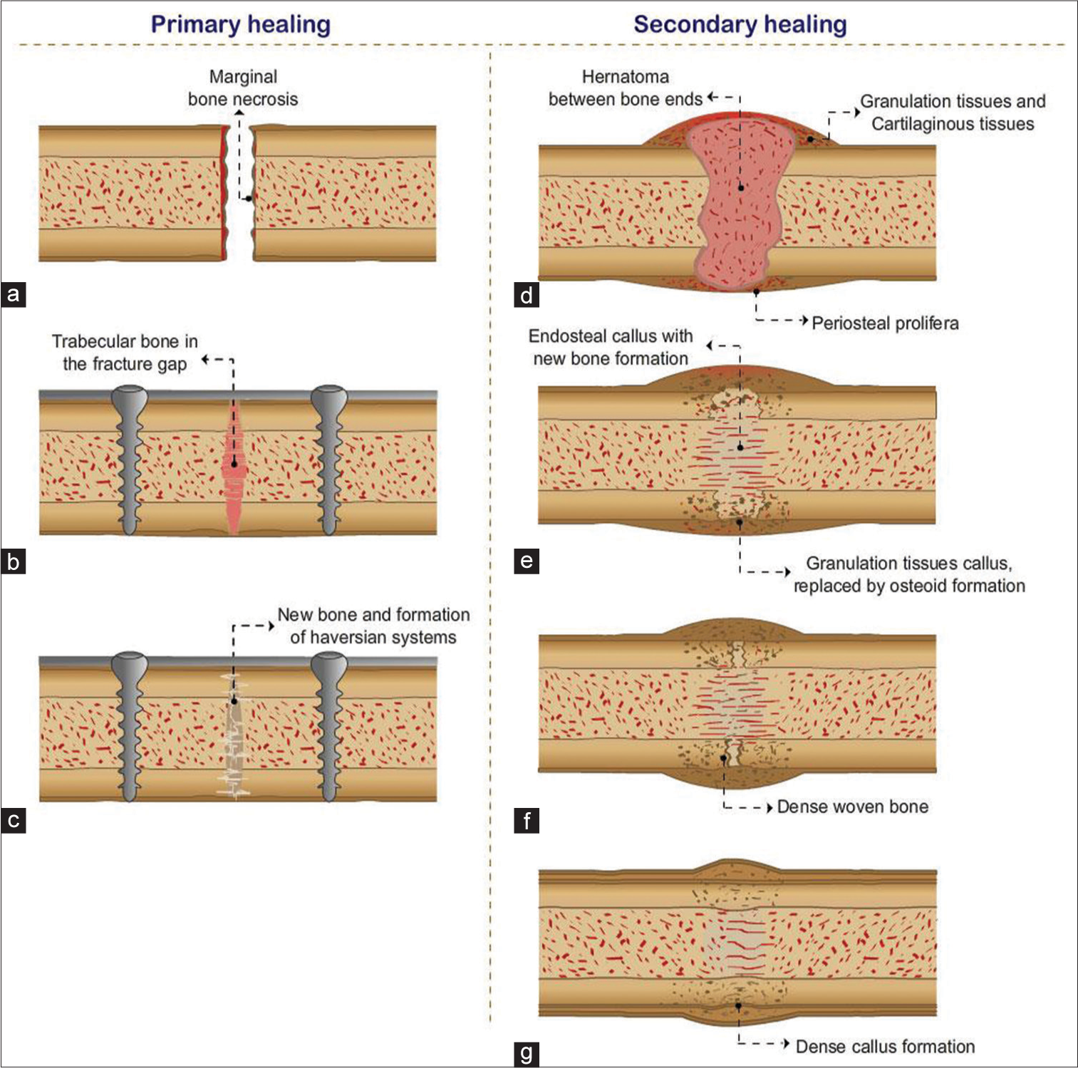
- Primary healing (a-c) is shown with surgical treatment and implant placement, with healing occurring through Haversian system and no callus formation. Secondary healing requires hard callus formation and four stages are described (d) hematoma formation, (e) soft callus, (f) hard callus, (g) bone remodeling.
Secondary healing is seen when fractures are managed conservatively, when fracture fragments are not significantly displaced, immobilization with the use of casts and splints, or when the fracture is restored through closed reduction and manipulation. This type of healing is also seen in postsurgical intervention with intramedullary nail (IMN) fixation or when bridging plates are used without screw fixation at the fracture site.
Primary healing of a fracture without callus formation occurs when fractures are surgically treated by internal fixation using implants such as plates and screws. The gap between the fracture fragments is significantly reduced. The fracture healing is initiated by the Haversian system of remodeling, the functional unit of cortical bone. The osteoclastic cells are seen at the tips of the multiple layers of the lamellar bone which resorb the ends of the fracture. Osteoblasts follow them, forming new bone, and laying down microscopic bony bridges across the fracture site. This method of healing is often preferred due to the significantly reduced healing time [Figure 1].[1,2]
Internal fixation is performed when adequate alignment cannot be achieved by conservative management alone or with fractures that are notorious for responding poorly to conservative management. This is achieved by open reduction and internal fixation (ORIF), wherein the fracture fragments are closely opposed to each other and held in place by surgical implants.[2]
External fixation is used in complex fractures where pins are placed through the skin and held in place by an external “scaffold.” This method may serve as a provisional fixation before internal fixation or as a definitive method of fixation.[3,4]
Indications for ORIF are listed below.[5,6]
Indications
Unstable fractures
Failed conservative (nonoperative/closed) management
-
When closed methods will probably fail:
Avulsion fractures that disrupt the muscle–tendon or ligamentous functions of the affected joint, like patellar fractures.
Fractures known to respond poorly to nonoperative management, like femoral neck fractures
Displaced intra-articular fractures
Pathological fracture
Polytrauma
Unstable open fractures
Fractures in young patients with a risk for growth arrest, like Salter-Harris types III–V
Associated neurovascular injury
When it will minimize confinement to bed
When the cost of overall treatment can be significantly reduced.
Contraindications for surgical fixation of fractures:
Any active inflammation/infection (local or systemic)
Compromised overlying soft tissues either due to injury or other unrelated causes
Contraindications to surgery or anesthesia
Limb salvage is almost impossible and amputation is a better option.
As radiologists, we need to consider a few technical requirements for imaging these surgical devices/implants:
Conventional radiology is the imaging modality of choice
A minimal of two orthogonal views need to be obtained
The radiographs should cover both joints above and below the implants or at least one joint closest to the fracture
The entire length of the implant should be identified, trying to include normal bone above and below it
With computed radiography and digital radiography systems, image manipulation can be easily performed. With Computed Tomography (CT) scan, 3D images can be obtained and metal artifact reduction techniques/ software need to be utilized to prevent/reduce artifacts
Comparison with previous imaging is mandatory.
Orthopedic fixation devices: can be categorized as internal and external fixators.
Internal fixators include screws, plates, IMNs, rods, wires, and pins. External fixators can be divided into different subcategories - uniplanar, multiplanar, unilateral, bilateral, and circular fixators.[4]
INTERNAL FIXATORS
SCREWS
Key factors that promote fracture healing are the limitation of interfragmentary movement and close apposition of the fracture fragments. The apposition of the fractured ends, reduced intervening fracture gap and fracture stability provided by the hardware facilitates and promotes healing. This compression at the fracture can be static or dynamic. In the static type, the compression is obtained by the implant itself, whereas in dynamic compression, the muscle/ligaments and/or body weight also provide additional compression.[5,7]
Screws are one of the most commonly utilized devices, used individually or along with other devices, and look exactly like those used in our daily lives for non-surgical chores. They can be placed across the fracture fragments, with the torsional forces compressing the fragments together, promoting healing. When used individually, the screws should be perpendicular to the fracture line for adequate compression. When more than one screw is used to fix two fragments, the screws should be placed divergent than convergent to provide better rotational stability. However, it is suggested to use them in conjunction with other devices to protect them from bending, axial, or rotational forces.[5,8]
While it is thought that screws were first used by Archimedes for irrigation, the essential properties of bone screws were published by Sherman in 1912.[8]
Screws can be classified according to their characteristics.
Design
Conventional screws
Locking screws
Headless screws
Cannulated, etc.
Single- versus double-lead threads
Material
Stainless steel
Titanium – these appear more radiolucent compared to stainless steel screws
Bioabsorbable
Size
3.5 mm
4 mm
4.5 mm
6.5 mm, etc.
Characteristics
Self-tapping: Have cutting flutes
Non self-tapping: Have smooth and conical tips
Self-drilling
Self-drilling and self-tapping
Area of application
Cortex
Cancellous
Malleolar
Function/Mechanism
Neutralization screws – to neutralize the forces in plate fixation
Lag screws – for interfragmentary compression
Cannulated screws – have a hollow core which are threaded over K-wires using the Seldinger technique
Reduction screws – to reduce a displaced fracture by pushing or pulling
Position screws – holds fragments in position without compression
Anchor screws – anchor for wires or sutures, for example, tension band wiring
Locking head screws – screw heads are threaded and can be locked into the plate
Locking screws
Poller screw – to guide the nail path while interlocking nailing of fractures close to bone ends [Figures 2a and b, 3].
Screw structure
Core – This is the solid section from where the threads project outwards. The size of the drill bits used to drill is the same as the core diameter. The size of the core also determines its strength and fatigue resistance [Figure 4].
Threads – The maximum diameter is the thread diameter while the thread depth is half of the difference between the thread and core diameter. The amount of contact with the bone is determined by the depth which in turn determines the resistance to the pullout. The pitch is the distance between each thread, which determines the distance travelled by the screw in one full turn (lead).
Head – This prevents the sinking of the screw into the bone. They may be threaded (locking) or plain. They are often used with a washer.
Tip – May be blunt, trocar, corkscrew, or self-tapping.
Difference between cortical and cancellous screws
[Figure 5 - Radiograph showing the difference].
Cortical screws:
Anchor in the cortical bone
More threads – smaller pitch
Thread to core diameter is less
Designed to have a better purchase in the cortical bone
Fully threaded
Cancellous screws:
Anchor in the soft cancellous bone
Larger pitch
Greater thread depth
Thread diameter to core diameter is more
Designed to have a better purchase in the cancellous bone
Partially or fully threaded
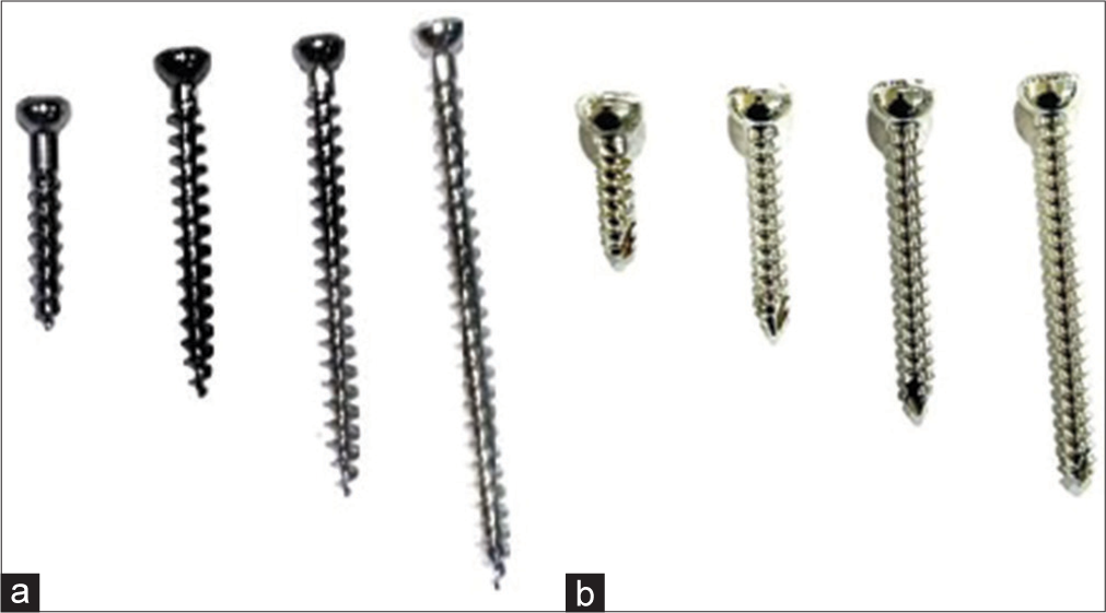
- Fully threaded cancellous (a) and cortical screws (b). Note the difference in the pitch.
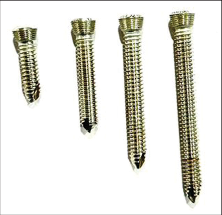
- Locking screw.
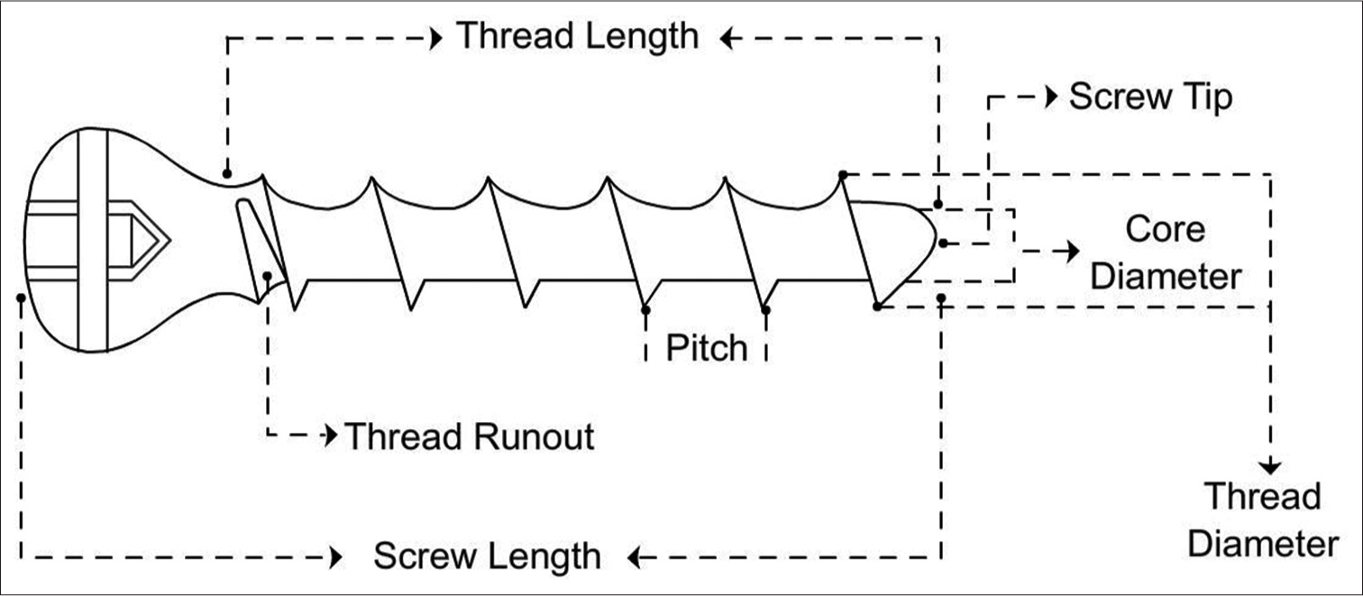
- Line diagram of screw structure.
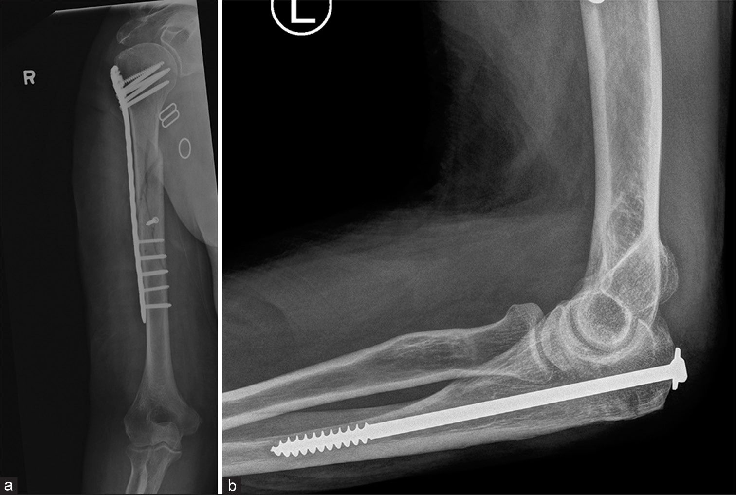
- (a) Fracture mid shaft of humerus showing dynamic compression plate with cancellous screws in the head and cortical screws in the shaft. Note the interfragmentary screw in the midshaft to hold and compress the reduction (b) partially threaded cancellous screw used to treat fracture of olecranon.
Locking head screws: These have larger core diameter with shallow threads and blunt edges.
The strength of screw fixation is not only dependent upon the density and quality of the bone but also on the strength of the screw material. The area of contact of the threads with bone depends on the pitch and thread design. The design of the screw head and the technique of the screw insertion are also important.
Special screws
Headless screws
Herbert screws: The distal and proximal ends have different pitches (greater pitch proximally than distally), allowing for greater interfragmentary compression. Often used in scaphoid fractures [Figure 6].
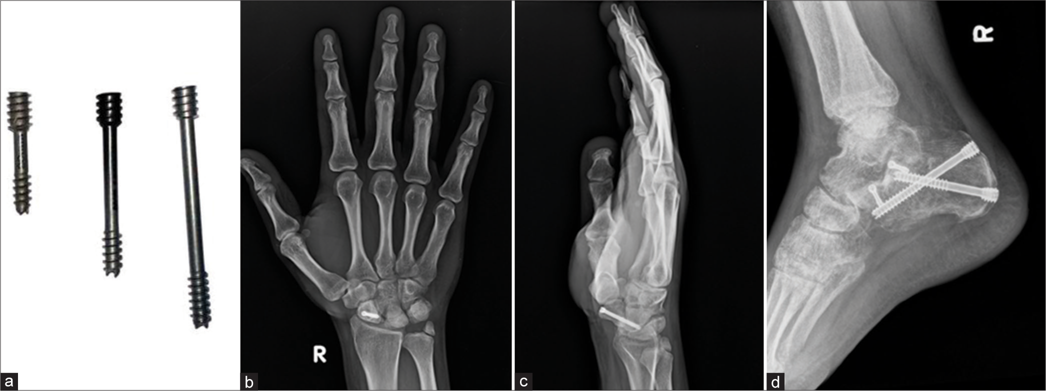
- (a) Herbert screws (b and c) anteroposterior and lateral views of the right wrist showing Herbert Screw in scaphoid fracture. Also note the non-united ulnar styloid fracture. (d) Lateral view of the ankle. Herbert screws used in fracture calcaneum. Note that the larger width and greater pitch proximally than distally. Hence as the screws closes in to the bone, the differential pitch allows greater compression at fracture site.
Acutrak screws: Acutrak screws are also used for scaphoid fractures. They, unlike Herbert screws, are fully threaded with a greater pitch at the tip and a smaller pitch proximally.
AO headless screws: AO headless screws resemble Herbert screws with a small central shaft. However, the pitches at both ends are the same [Figure 7].
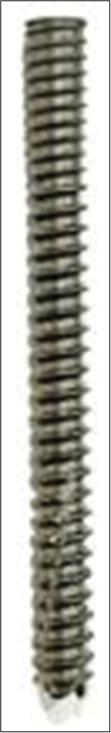
- AO Headless screw.
Bioabsorbable screws
Interference screws were first introduced by Lambert in 1983.
Advantages
Don’t need to be removed
No artifacts on magnetic resonance imaging (MRI)
Don’t interfere with revision surgery, if required
Decreased incidence of graft laceration.
Disadvantages
Failure during insertion. Special screws are required that can span the entire length of the track, reducing the breakage
Foreign body reactions, though uncommon, can be seen.
These are radiolucent on radiographs and identified by the bone tracks made by the drill bits. It is important to identify this radiolucent track around the screws during follow-up and compare it with previous radiographs. Any progressing radiolucency or widening/diverging of the track is suggestive of a failing implant, instability, or sometimes infection.
Interference screws can also be made of titanium [Figures 8 and 9]
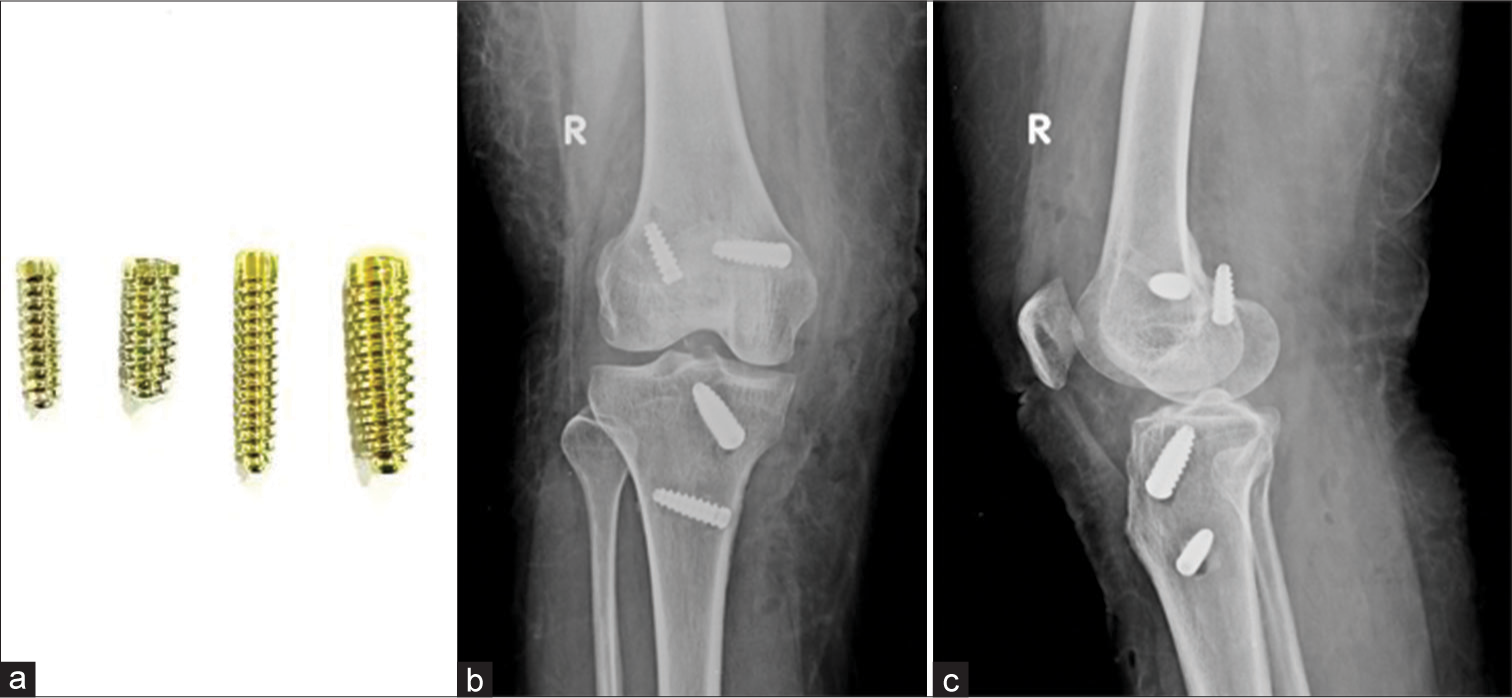
- (a) Titanium interference screw. (b and c) AP and Lateral radiographs of the knee. Post anterior cruciate ligament and middle collateral ligament reconstruction with titanium interference screw in situ. Note that the femoral screw in the lateral condyle on lateral view has breached the cortex.
- AP (a) and lateral (b) radiographs of the knee showing Post anterior cruciate ligament reconstruction performed using bioabsorbable screws. The grafts used for ligamentous reconstruction are placed within these tunnels and held by these screws. These tunnels can be identified as radiolucent, parallel tracks. Also identify the radio-opaque endobutton along the lateral femoral cortex at the femoral tunnel.
Suture anchors
Most anchors are made of titanium, biostable Polyetheretherketone, or biodegradable HA-coated PolyL-Lactic acid. They are used to attach soft tissues (muscle, tendon, ligament, etc.) to the bone and have become essential in sports surgery and arthroscopy. In the shoulder, they are used to pull in labral tissue or imbricate the capsule to the glenoid. The hold of the anchor to the bone is called the pullout strength. An anchor placed at an angle of 45° holds the best in bone [Figure 10].
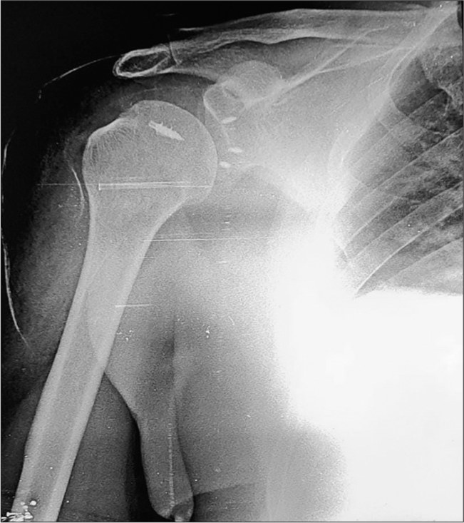
- Anteroposterior radiograph of the right shoulder post arthroscopic surgery for anterior instability (Bankart fixation and humeral remplissage). Note the titanium suture anchors in the humeral head (5 mm) and glenoid (2.8 mm). Suture anchors are screw like structures with suture threads loaded into them used to anchor soft-tissue to the bone.
One should remember that to place a screw, whether individually or with another component, a hole has to be made, which essentially weakens the bone. Furthermore, the load bearing falls more on the screw, with resultant osteopenia in the adjacent bone because of the “stress shielding.” From a surgical standpoint, the weakening of the bone may lead to increased stress on the hardware, resulting in implant failure. As a radiologist, we should be able to identify abnormalities in the bone and the hardware as the earliest. Remember, hardware should be removed at the earliest, allowing the formation of new bone which, in turn, strengthens it.
WASHERS
These provide an additional surface over the fixation screw, distribute the stress, and prevent the breakage of cortical bone. Serrated washers are also used for fixing avulsed tendons, small avulsion fractures, or comminuted fractures of the remainder of the bone.[5,9]
PLATES
Plates along with screws have been continuously undergoing remodifications since their introduction. The tension band principle was first defined and applied to fractures and non-unions by Friedrich Pauwels who explained how tensile forces are converted to compression forces when applied to the convex side of an eccentrically loaded bone. This is achieved by placing a bone plate (the tension band) across the fracture on the convex aspect of the bone. This counteracts the tensile forces, converting them to compression forces. If this plate was applied to the concave (compression) aspect, it would likely bend, develop fatigue or fail.[10] Recent research has also shown that these plates need not be completely rigid, allowing the use of more flexible plates as micromotion at fracture sites promotes a combination of both primary and secondary healing, resulting in faster healing of the fracture.[11]
Advantages
Anatomic reduction through an open technique
Stability for early remobilization.
Disadvantages
Premature weight bearing leads to failure
Risk of refracture after removal
Stress shielding and osteoporosis beneath the plate
Plate irritation
Foreign body reaction - rare.
Types of plates according to function
Neutralization plates
Compression plates
Buttress plates
Bridge plates
Specific plate designs
Tubular plates, T, L, reconstruction, spoon, dynamic compression plates (DCP), locking compression plates (LCP), limited contact DCP (LC-DCP), and limited contact LCP plates (LC-LCP).[10]
Neutralization plates are not special plates. Instead, the name explains its function. These plates span the fracture and reduce the load, which is now transferred to the plate. They are designed to protect the fracture surfaces from rotational, bending, and axial shear forces. They are often used along with interfragmentary/lag screws in a wedge or butterfly fragment fractures. Common fractures fixed using neutralization plates are wedge fractures of the humerus, radius, ulna, and fibula.[5,7,10]
Compression plates are usually used to apply compression to fractures.[7] They may provide dynamic compression when used along the convex aspect of the bone. The DCP is recognized by the oval screw holes which have beveled floors with inclined surfaces in which, the screws are placed eccentrically As the screws are tightened, the surfaces pull the ends of the bone together[5] [Figure 11].
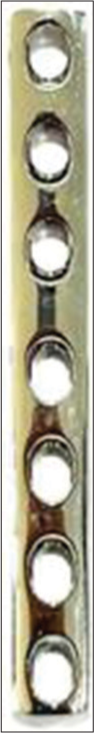
- Dynamic compression plate (small).
It was suspected that the compression plates could compromise the periosteal blood supply, delaying the healing. Thus, LC-DCP was devised. These plates have undercuts under each and between the adjacent screw holes, reducing the contact of the plate with the bone, thus not compromising the blood supply and promoting healing[5] [Figure 12].
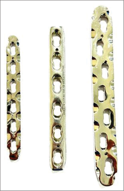
- Low contact dynamic compression plate.
Buttress plates, unlike compression plates (that create compression across a fracture site), negate compression, and shear forces. These are designed to rigidly hold fracture fragments at the ends of the long bones – epimetaphyses, especially at the knee and ankle where the fracture sites undergo compression. They are often used as a supplement to lag screw fixation of metaphyseal shear or split fractures. The lag screws may be inserted through or outside the buttress plates[12] [Figure 13].

- (a) Buttress plate (b) Anteroposterior view of the knee showing fracture of the proximal tibia with buttress plate in situ. Note cancellous screws in the proximal aspect while cortical screws have been used in the diaphysis.
Buttress plates, also known as peri-articular plates, are broadened and contoured at the ends of the joints. As the ends of the joints have several surfaces, these plates are contoured to a particular surface (medial or lateral or anterior, etc.), resulting in several designs for an individual joint. The most common type of plate configurations is T-shaped, L-shaped, and bulbous end shaped plates. They help hold the retracted and depressed fracture fragments, once elevated. The plates are anchored in the main stable fragment, but not necessarily to the fragment it is supporting.[5,7,10]
Blade plates have an oblique or right angle and are designed for subtrochanteric femoral fractures or supracondylar fractures of the femur. One arm of the plate has a chiseled shaped end that is used to bridge the fracture, while the other arm is used as a side plate and anchored through multiple screws into the bone[5] [Figure 14].
- Angle blade plate.
In unstable fractures or fractures in which anatomic reduction or rigid stability cannot be achieved due to bony defects or where intramedullary nailing or conventional plate fixation is not suitable, bridge plates are used. These plates span the fractures, often along with autologous bone grafts providing relative stability, length, and alignment.[7,10] The blood supply to the fracture fragments is also preserved as the fracture site is undisturbed during the surgery, allowing secondary healing with callus formation. Micromotion is also noted at the fracture site.[11,13]
Concave plates have a concave bend towards the bone and are used in transverse fractures producing compression forces on both the near and far end of the cortices around the fracture. They are most commonly used in the humerus.
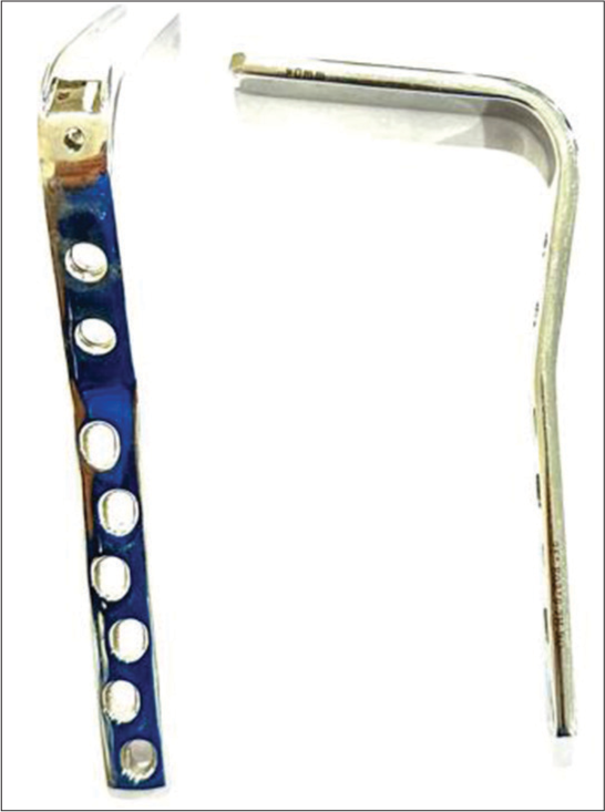
Reconstruction plates have deep notches on both sides and in the middle between the two holes. These can be bent in various directions to match the anatomic shape of the bone. They are, however, less durable and are used in clavicular and pelvic fractures [Figures 15 and 16].
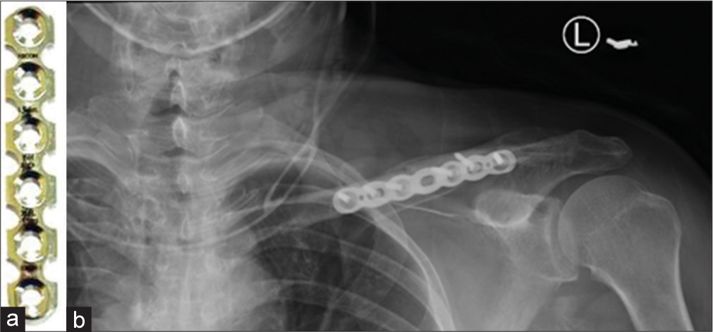
- (a) Reconstruction plate (b) anteroposterior radiograph showing reconstruction plate used for fracture mid shaft of the left clavicle.
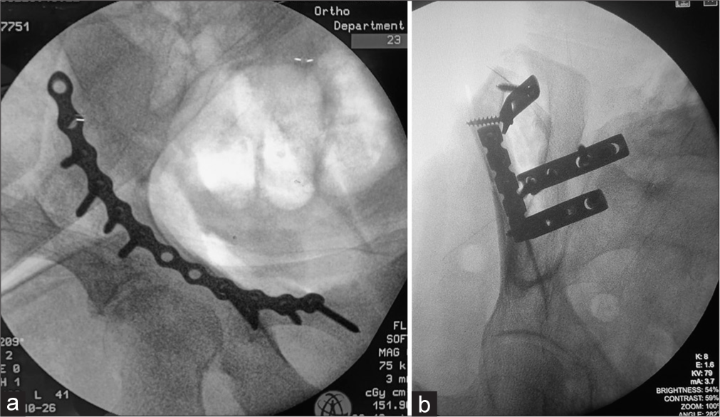
- Fluoroscopic figures showing (a) reconstruction plating of the anterior column of the acetabulum via anterior intrapelvic approach (b) acetabular anterior column pelvic fractures fixed with reconstruction and dynamic compression plates. Note the difference in borders. The notching on the reconstruction plate allows sidewards bending and curving of the plate on uneven surfaces.
The term locking versus non-locking plates is also used often. Locking plates use locking screws that have threads in the heads which become fixed in the plates compared to the conventional screws (without threads). The locking head screws are more stable in the osteoporotic bone as there is a reduced risk of screw pull out and overtightening. Reduced fractures tend to stay reduced. Other advantages include uncompromised periosteum as the plate is not pressed against the bone. These plates also do not need to be perfectly contoured to the bone.[13]
Plates can be fixed using bicortical or unicortical screws. As the name suggests, uni-cortical screws remain in the proximal cortex while bicortical screws enter both cortices. Bicortical screws are used more commonly and are generally used in all conventional plating for the fixation of diaphyseal fractures. A bicortical fixation offers better purchase of the screw in bone and greater torque is required for screw pullout. New generation plate systems allow a unicortal fixation. The advantage is only that when implant removal is done, refracture chances are more in bicortical than uni-cortical fixation.
The plating method often involves anatomical reduction of the fracture first giving absolute stability in the absence of comminution of the fracture site. Healing in such fractures does not show callus formation (primary healing) and thus has to be assessed in the absence of fracture lines. It is important to assess the plate and look for any step-off in its contour, suggesting plate fracture. This usually occurs at the screw hole, which is the weakest link. Plate fractures are often seen in one view only; hence, it is important to assess the plate from both views.
WIRES
Cerclage wires
These are stabilization/fixation wires used to approximate bone fragments by encircling them. While they can be used alone, they are more often used in conjunction when treating fractures with intramedullary pin placement. They are often used in long oblique or spiral fractures where at least two wires can be placed. Care must be taken to place these away from the tips of the fragments [Figure 17]. They are not used for short oblique fractures as they generate larger shearing forces, causing loss of reduction, and fracture to shear and collapse.[14]
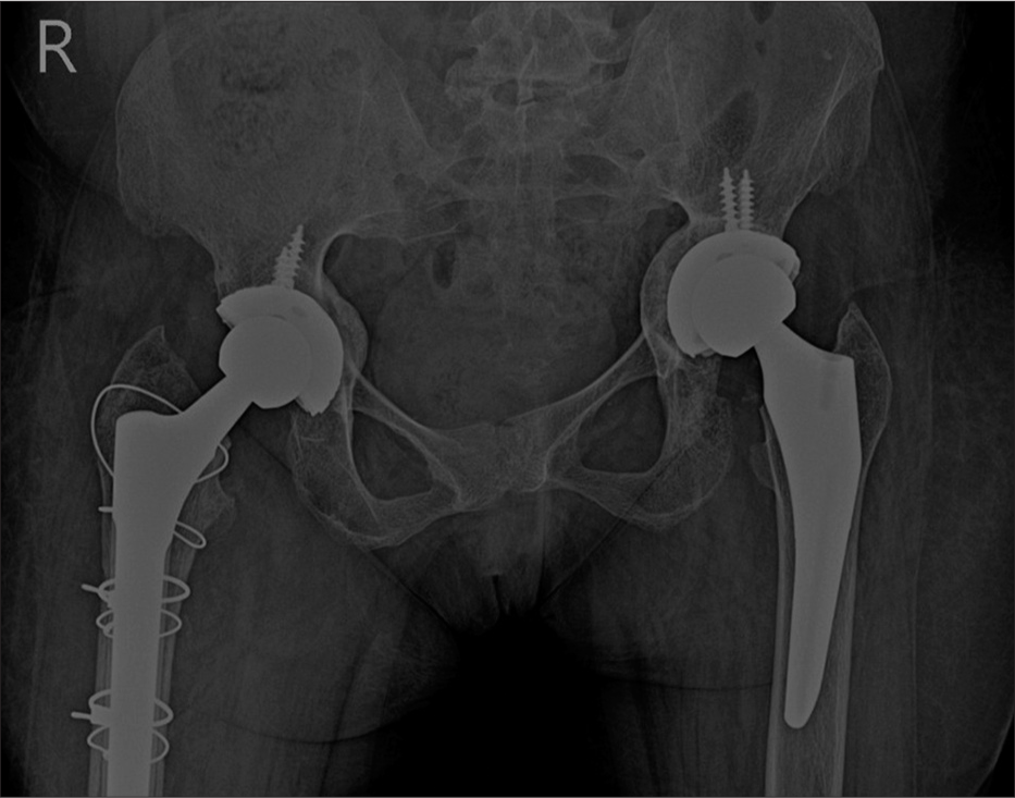
- Anteroposterior radiograph of the pelvis showing bilateral total hip replacements with cerclage wires placed along the right femur for periprosthetic fracture.
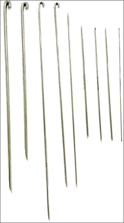
Kirschner or K-wires
These are thin pins and are often used as an alternative to screws for the fixation of fractures of small bones such as phalanges, metacarpals, metatarsals, and multiple small articular fragments in comminuted fractures. They can be threaded over by cannulated screws and can also be used in combination with cerclage wire loops for tension band wiring.[1,5,11,15]
Indications
Epi-metaphyseal fractures, as defined by the AO classification
Fractures of small bones
Small bony fragments
Fragment reposition in multi-fragmentary fractures
Can be used for temporary or final stabilization.
Contraindications
They cannot be used alone in diaphyseal or multi-fragmentary fractures as they do not provide sufficient stability for early rehabilitation.
Advantages
Cheap
Easily available
Can be easily inserted and removed, under fluoroscopic guidance
Relatively atraumatic and can be used to treat fractures involving the physeal plate.
Disadvantages
They are not functionally stable.
A radiologist should assess and ensure the following:
The entry point for the wires should be as far apart as possible.
They should be as perpendicular as possible to the plane of the fracture.
The wire should never protrude >2–3 mm from the opposing cortex, reducing the risk of soft-tissue injury [Figure 18].
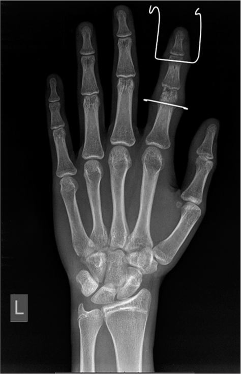
- Anteroposterior radiograph of the left hand showing fractures of the heads of the proximal and middle phalanges with K wires used as external fixation devices to maintain traction and reduction.
Tension band wiring
Tension bands use the same principle of bone plates converting tensile forces into compression forces. Remember that curved bones have a compressive, which is the convex aspect and tensile, which is the concave aspect. The tensile forces pull the bones apart.[16]
These can be used alone or with screws or K-wires.[5]
They are commonly used in fractures of the patella and olecranon where during flexion the normal pull of the quadriceps and triceps tendons, respectively, pull the fracture fragments apart. Wire loops forming “figures of 8” are placed, converting the tensile forces to compression forces. Avulsion fractures of the greater humeral tuberosity are also similarly treated.
Static tension bands produce compression at the time of application, as the forces at the fracture site are fairly constant during movement, for example, at the medial malleolus.
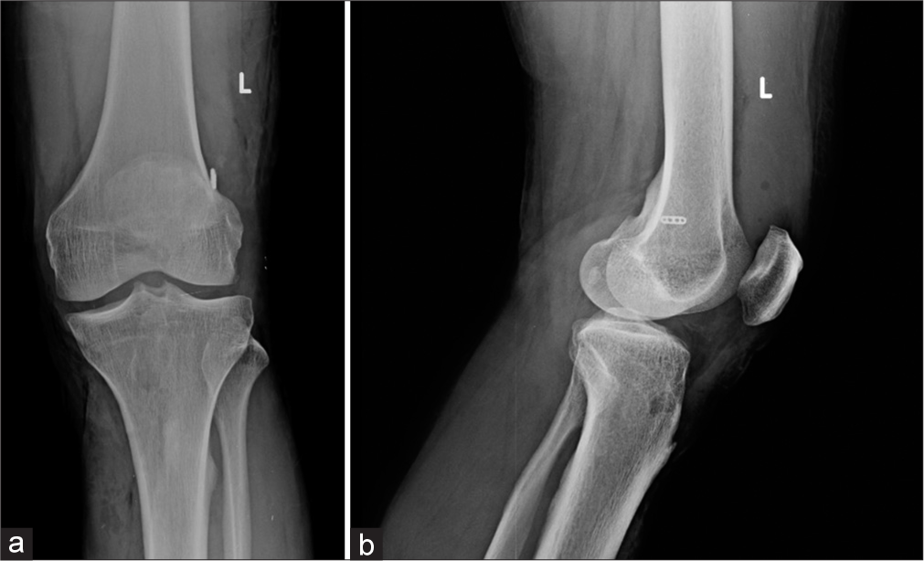
Dynamic tension bands increase the compression force as the motion increases, such as those used in patellar and olecranon fractures [Figure 19].[16]
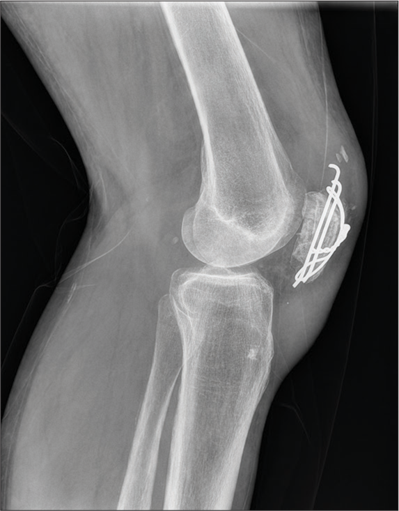
- Lateral radiograph of knee with tension band wiring for patellar fracture.
IMNs and Rods
From the use of wood, ivory, and now metals, the IMNs have evolved over time. Gerhard Küntscher is credited as the founding father of the modern day IMN during World War II in 1939.[17,18]
They are commonly used to treat fractures of the long bones. As the name suggests, these rods are placed in the medullary cavity of the bone. Acting as an internal splint, they stabilize the fracture causing minimal damage to surrounding tissues. Because of their strength and shape, they can withstand the heavy load of the body, allowing early remobilization after surgery, before the bony union.
The working length of the nail is the length that transmits the load between the fractured fragment. The longer this working length, the greater the relative movement between these fragments.
These can be solid or hollow. While solid nails are stronger, hollow ones are less stiff giving a little flexibility to the implant, making it easier to insert and also allowing the nail to conform to the natural shape of the bone [Figure 20a and b].[18]
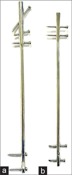
- (a) Intramedullary nail for femur (b) intramedullary nail for tibia.
Advantage of intramedullary nailing over plate and screw fixation
As they are aligned with the central axis of the bone, they undergo smaller bending loads, reducing the stress fatigue
They behave as load sharing devices. When the nail is not locked by screws at the proximal and distal ends, it acts as a gliding splint, allowing the compression of the fracture fragments while load bearing
Stress shielding is not seen
Refracture after implant removal is rare
Placement is easier and performed in a “closed” technique under fluoroscopic guidance, lowering infection rates and soft-tissue injury with better chances of union.
Indications
Extra-capsular fractures of the proximal femur
Transverse and short oblique fractures of the tibial and femoral shafts
Humeral shaft fractures
Metaphyseal fractures
Comminuted fractures of the tibia and femur
Pathological fractures
Delayed or non-union of the femur or tibia.
Contraindications
Immature skeleton, to avoid damage to the open epiphyses
Prior malunion with deformed bone
Small medullary canal
Infected fractures
Associated femoral neck fractures
Fracture in line of the locking screws
Hypovolemia, hypothermia, and coagulopathy are absolute contraindications.
Interlocking nails
These are well suited for diaphyseal fractures. If associated with metaphyseal or periarticular fractures, a diaphyseal nail alone offers little control. Although these nails are designed for periarticular fixation, they often require screws and plate construction. Typically, they are locked proximally and distally with two or more bolts to provide rotary control of the fracture. They are commonly used in femoral and tibial fractures and less commonly for the humerus and forearm. They are usually avoided in the immature skeleton. Present day interlocking nails are hollow [Figure 21].[5,7,18]
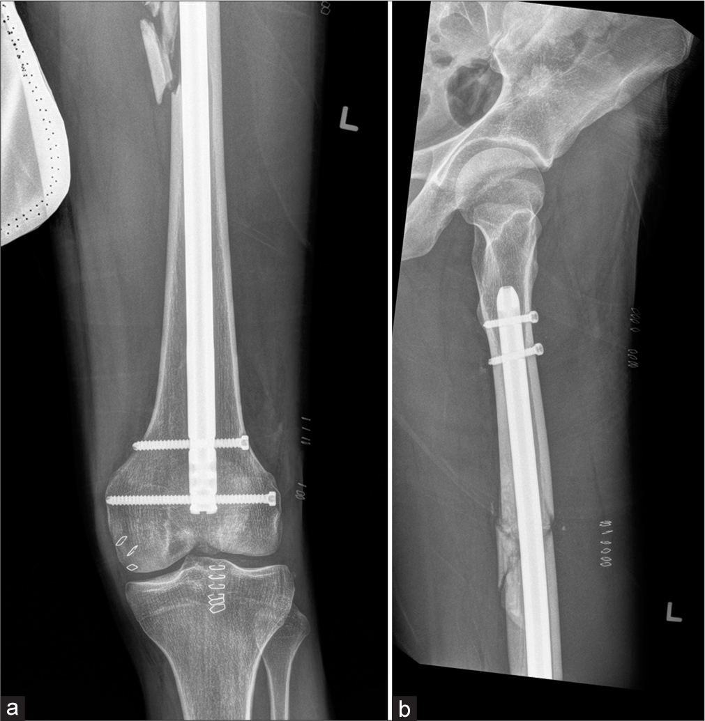
- (a) Anteroposterior radiograph of the distal thigh with knee and (b) lateral radiograph of the proximal leg with hip joint showing comminuted fracture of the mid shaft with interlocking nail in situ.
Elastic and rush nails
These IMNs have no option for locking and are used in immature skeletons. They are pre-bent before insertion and stacked in multiples based on the diameter of the medullary cavity, providing “three point” fixation and stability. They are also used as an adjunct to external fixators in compound fractures. Compared to interlocking nails they are of smaller diameter and are not hollow [Figure 22].[5]
- Rush nails.
Complications of intramedullary nailing[18]
Infection
Compartment syndrome
-
Implant failure
Fractures adjacent to the metaphysis
Incorrect nail diameter
Early weight bearing
-
Limb shortening
Dynamic interlocking with excessive weight bearing
Corrective measures are required if the discrepancy is >1.2 cm.
Malunion
Heterotopic ossification
Soft-tissue injury and irritation over the entry point – usually seen with a longer nail.
It is useful to note the insertional points of nails on follow-up (usually proximal or distal). Proximal migration indicates an unstable construct and possible non-union. As already mentioned, IMNs are load-sharing devices where the load passes both through the nail and fracture site. They offer relative stability unlike plates which give absolute stability and are load bearing. Often during the healing process, we can see a lucent line around the nail with a sclerotic border indicating micromotion at the fracture site. This micromotion with protected weight bearing stimulates fracture union, which is seen as bridging callus in follow-up. On the other hand, macro motion at the fracture site leads to hypertrophic callus, implant strain, and non-union.
Future of IMNs
IMNs have gone through several changes since their introduction in the 16th century. Novel IMN designs now include growth factor and/or antimicrobial coatings promoting fracture healing while reducing the risk of infection; minimally invasive expandible IMNs avoiding the use of interlocking screws and new materials such as carbon fibre for superior biochemical properties and reduced artifacts on computed tomography (CT) and MRI imaging. The newer novel IMNs also aim to reduce the operative time and radiation exposure. A lot of future research is needed to achieve the status of the “perfect” IMN.[17]
Femoral fractures
A special mention of femoral fractures is necessary as these are the most common fractures treated surgically. The dynamic hip screw (DHS), also known as the sliding hip screw, is likely the most common device used for the femoral neck (extracapsular) and intertrochanteric fractures and sometimes subtrochanteric fractures. It consists of a side plate that is fixed to the distal femur via cortical screws with a lag screw which is placed via a hollow metal barrel in the neck. The position of this screw should be within the exact center of the neck and head with the tip in the subchondral region of the head[5] [Figure 23].
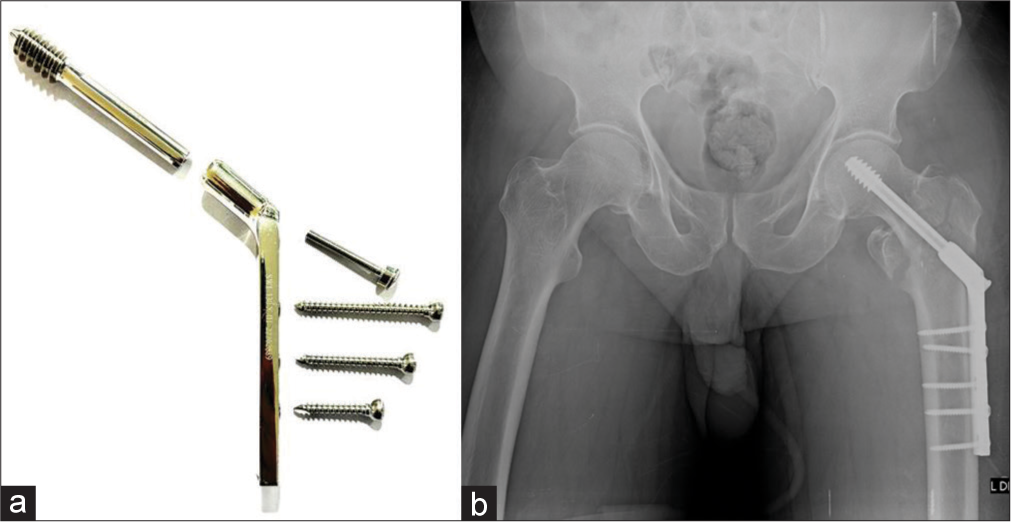
- (a) Dynamic hip screw (DHS) system (b) anteroposterior radiograph of the pelvis with intertrochanteric fracture status post-surgery with DHS.
Proximal femoral nails are also frequently used for intertrochanteric fractures with lesser complications and faster mobilization post-surgery [Figure 24].
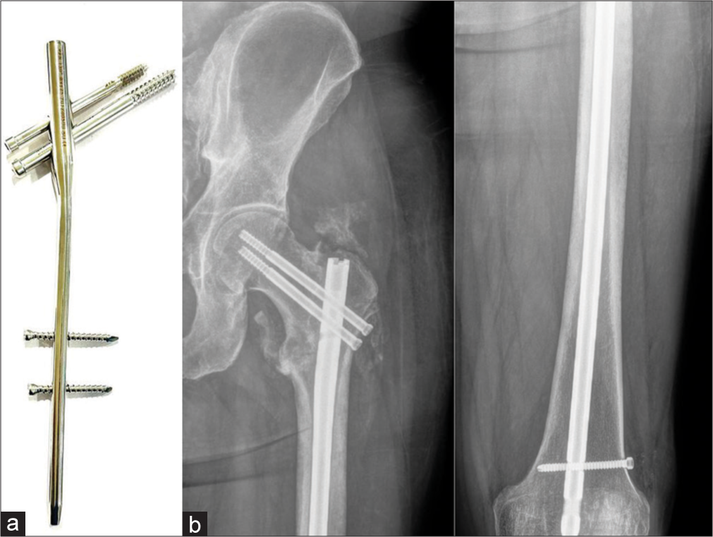
- (a) Proximal femoral nail (PFN) system (b) anteroposterior radiographs of the left hip joint and femur showing peritrochanteric fracture with PFN in situ. Note the central position of the screws. With the routine intramedullary nail only diaphyseal fractures can be fixed. With this system, peri trochanteric fractures can also be fixed. Note the peritrochanteric heterotopic ossification.
In nondisplaced transcervical fractures in the elderly or displaced transcervical fractures in young patients, parallel, cannulated screws are preferred, as they are less traumatic compared to the DHS, with reduced risk to the blood supply in the proximal head and neck.
One should look for any subtle changes in the position of the screws or periprosthetic lucencies to forewarn the orthopedic surgeon.
Subtrochanteric fractures are however, a bit more difficult to treat than intertrochanteric fractures. The muscles act as deforming forces on the proximal and distal fragments resulting in abduction, external rotation and flexion of the proximal segment and adduction of the distal segment. Thus, surgical management is the preferred option. IMN is now the gold standard for their treatment.[5,19,20]
EXTERNAL FIXATION
External fixators have been described by Hippocrates, more than 2000 years ago as a method to immobilize fractures. While the design of the external fixators may have evolved over the years, the primary goals remain the same, which are to preserve the limb length, the alignment and the rotation of the fracture fragments. External fixators can function as provisional or definitive fixators and provide a secondary form of bone healing.
These can be divided into uniplanar, multiplanar, unilateral, bilateral and circular types. In the multiplanar construct, multiple pins are placed perpendicular to each other, resulting in a sturdier fixation compared to uniplanar types. Additional stability can be added by placing pins on both sides of the bone in the bilateral frame type. Circular fixators are generally used in limb lengthening procedures, along with the patient weight bearing some movement at the joint [Figure 25].
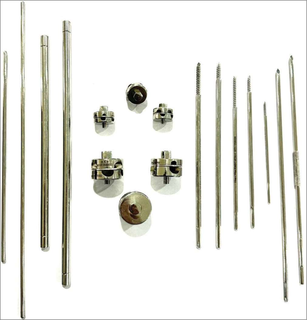
- External fixator components.
The procedure is minimally invasive and generally safe. A thorough knowledge of anatomy facilitates the prevention of injury to the neurovascular structures.
Indications
Unstable pelvic ring fractures
Comminuted periarticular/long bone fractures
Fractures associated with significant soft tissue swelling
Hemodynamically unstable patients
Fractures with significant bone loss
Open fractures with significant soft-tissue loss
Limb lengthening procedure
Osteomyelitis with/without bone loss
Immobilization of joint after soft-tissue flap
Arthrodesis
Non-union/malunion
Traction.
Contraindications
Relative contraindications include obese patients where placement of pins may be difficult; where poor compliance is expected; limited bone stock for pin placement.
Complications
The complications are similar to other implants, but, pin site infection is very common as the procedure is generally performed in open fractures with high predisposition to infection. Soft-tissue impalement and neurovascular injury are other complications.[4,5]
ROLE OF THE RADIOLOGIST
As a radiologist, if one can understand the basic mechanism of the fracture and its management, half the work is done. However, we play a more vital role in identifying/suspecting complications at an initial stage. Therefore, it is imperative that every report should follow a standard checklist which needs to be documented in the interpretation:
Type of fracture and surgical management
Bone alignment/malalignment, if any
Displaced fracture fragments, especially on CT
Fracture healing
Position of implant/malpositioning
Signs of hardware failure such as malalignment and angulation fracture.
Soft-tissue abnormality, if any.
Comparison with the previous radiographs is mandatory as it allows the radiologist to identify subtle changes and early/ overt complications.
CONCLUSION
The authors hope that this article will help radiologists familiarize themselves with the various types of basic orthopedic hardware, and their use in orthopedic practice. This understanding will help radiologists provide an appropriate interpretation of the imaging findings of various types of implants and their failure.
In the next section of this article in the forthcoming edition, we plan to describe the various complications of hardware/ implants encountered by the radiologist and will provide tips on how to recognize them.
Acknowledgment
We wish to thank Ms. Anita Pateriya for her patience and help with the Figures.
Declaration of patient consent
Patient’s consent not required as patients identity is not disclosed or compromised.
Conflicts of interest
There are no conflicts of interest.
Financial support and sponsorship
Nil.
References
- Orthopedic Hardware and Complications In: Basic of MSK Imaging. United States: McGraw Hill Education; 2013. p. :211-33.
- [Google Scholar]
- Fracture healing overview In: StatPearls. Treasure Island, FL: StatPearls Publishing; 2022. Available from: https://www.ncbi.nlm.nih.gov/books/NBK551678 [Last accessed on 2022 May 08]
- [Google Scholar]
- External fixation principles and overview In: StatPearls. Treasure Island, FL: StatPearls Publishing; 2022. Available from: https://www.ncbi.nlm.nih.gov/books/NBK547694 [Last accessed on 2022 Feb 12]
- [Google Scholar]
- Orthopedic Hardware UW. Available from: https://www.rad.washington.edu/about-us/academic-sections/musculoskeletalradiology/teaching-materials/online-musculoskeletal-radiology-book/orthopedic-hardware [Last accessed on 2022 Sep 01]
- [Google Scholar]
- General Principles of Fracture Care and Treatment. Available from: https://www.emedicine.medscape.com/article/1270717-treatment [Last accessed on 2022 Sep 01]
- [Google Scholar]
- A Brief Introduction into Orthopaedic Implants: Screws, Plates, and Nails Canada: University of Calgary; 2012. p. :1-19.
- [Google Scholar]
- Available from: https://www.orthopaedicprinciples.com/2013/06/bone-screws-in-orthopaedic-surgery [Last accessed on 2022 Sep 05]
- Radiological evaluation of internal fixation devices in the upper limb. Rev Argent Radiol. 2017;81:285-95.
- [Google Scholar]
- Amputations of lower extremity In: Crenshaw AH, ed. Campbell’s Operative Orthopaedics. United States: Mosby; 1992. p. :740-60.
- [Google Scholar]
- Evolution of the internal fixation of long bone fractures. The scientific basis of biological internal fixation: Choosing a new balance between stability and biology. J Bone Joint Surg Br. 2002;84:1093-110.
- [CrossRef] [Google Scholar]
- Available from: https://www.surgeryreference.aofoundationorg/orthopedic-trauma/adult-trauma/basic-technique/basic-principles-of-plating [Last accessed on 2022 Sep 05]
- Available from: https://www.orthobullets.com/basic-science/9063/orthopaedic-implants [Last accessed on 2022 Sep 05]
- Available from: https://www.surgeryreference.aofoundation.org/vet/dog/femoral-shaft/further-reading/cerclage-wires-technique [Last accessed on 2022 Sep 07]
- Orthopedic hardware and equipment for the beginner: Part 1: Pins and wires. Can Vet J. 2011;52:1025-6.
- [Google Scholar]
- Tension Band Principles and its Applications. Available from: https://www.boneandspine.com/tension-band-principle
- [Google Scholar]
- Intramedullary nail: The past, present and the future-a review exploring where the future may lead us. Orthop Rev (Pavia). 2021;13:25546.
- [CrossRef] [PubMed] [Google Scholar]
- Intramedullary Nailing of Fractures. Available from: https://www.boneandspine.com/intramedullary-nailing [Last accessed on 2022 Sep 07]
- [Google Scholar]
- Subtrochanteric femur fractures: Current review of management. EFORT Open Rev. 2021;6:145-51.
- [CrossRef] [PubMed] [Google Scholar]
- Available from: https://www.orthobullets.com/trauma/1039/subtrochanteric-fractures [Last accessed on 2022 Sep 10]


