
Translate this page into:
Displaced meniscal tears using clock face method: A pictorial essay

*Corresponding author: Karan Asthana, Department of Radiology, Deenanath Mangeshkar Hospital, Pune, Maharashtra, India. karanasthana12@gmail.com
-
Received: ,
Accepted: ,
How to cite this article: Desai S, Asthana K, Kamesh G. Displaced meniscal tears using clock face method: A pictorial essay. Indian J Musculoskelet Radiol. 2024;6:75-8. doi: 10.25259/IJMSR_27_2023
Abstract
In this pictorial essay, we describe the position of the displaced meniscal fragment using the clock face method with an aim to guide the arthroscopist about its exact displaced location. Accurate diagnosis of meniscal tears and their displacements, along with their description, is imperative for arthroscopists to help with appropriate treatment. Using the clock face method for describing the displaced fragment, a uniform description of the displacements can be standardized.
Keywords
Meniscus
Knee
Clock
Face
Displaced
Flap

INTRODUCTION
The menisci are C-shaped structures formed of collagen fibrocartilage and serve many important functions, such as shock absorption, axial load distribution, and stability.[1]
Each meniscal tear can be characterized in relation to two planes. A tear is described first with respect to the meniscal circumference as either longitudinal (parallel to the circumferential collagen fibers) or radial (perpendicular to these fibers). Second, the orientation of a longitudinal tear is described as either vertical or horizontal with respect to the meniscal depth. Thus, there are three basic types or patterns of meniscal tear: longitudinal vertical, longitudinal horizontal, and radial.
Magnetic resonance imaging (MRI) is the imaging modality of choice, with sensitivity and specificity for depicting meniscal tears being 93% and 88%, respectively.[2]
These three basic patterns can produce displaced types of tears, including bucket handle tears, flap tears, and parrot beak tears. A combination of two patterns is referred to as a complex tear. Displaced meniscal tears are common, forming the majority of symptomatic meniscal lesions.[3] Displaced flap tears are those with displacement between normally fused segments. Flap tears involve the medial meniscus (87%) more than the lateral meniscus (13%). The most common flap tear is meniscal body tear, which displaces inferiorly into the medial gutter (67%). This cannot always be seen on arthroscopy but should be diagnosed on MRI.[4] Ensuring that meniscal tears are accurately diagnosed and receive appropriate management has been shown to result in economic benefits.[5] MRI is the most appropriate diagnostic investigation when such a tear is suspected.[6,7] Such displaced fragments must be identified at imaging, as they may be missed at arthroscopy if their location is difficult to visualize and the residual meniscal surface appears healthy. A clock face method for describing the position of displaced meniscal fragments can help standardize its radiological description and make its description unambiguous.
DISCUSSION
Method for describing the position of the displaced meniscal fragment
A clock face method was employed to document the location of the fragments.[8]
Using an axial image at the relevant level, which corresponds to the displaced meniscal fragment, was used. 12 o’clock was considered as anterior, and six o’ clock was considered posterior [Figures 1 and 2]. For both knees, three o’clock was considered medial, and nine o’clock was considered lateral displacement. If there was a large displaced fragment, the center of the fragment was used to define its clock position.
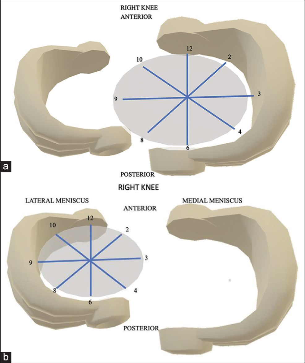
- (a) Pictorial representation of the clock position in the medial meniscus of the right knee. (b) Pictorial representation of the clock position in the lateral meniscus of the right knee.
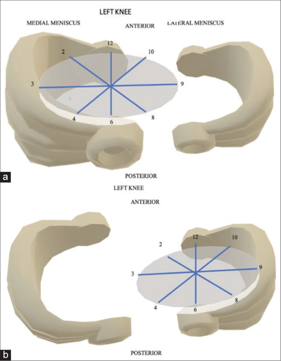
- (a) Pictorial representation of the clock position in the medial meniscus of the left knee. (b) Pictorial representation of the clock position in the lateral meniscus of the left knee.
Using the above-mentioned criteria, the displaced meniscal fragments were assigned clock position. These are shown in the representative images.
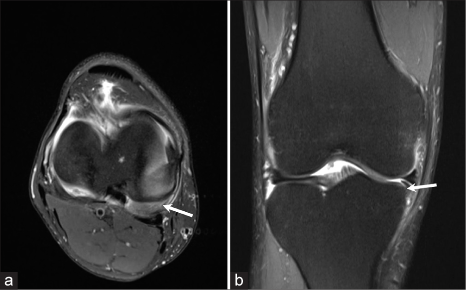
A displaced meniscal fragment arising from the posterior horn and body of medial meniscus of the right knee was seen at 5 o’clock position [Figure 3a]. This corresponded to the fragment being displaced in the inferior coronary recess [Figure 3b].
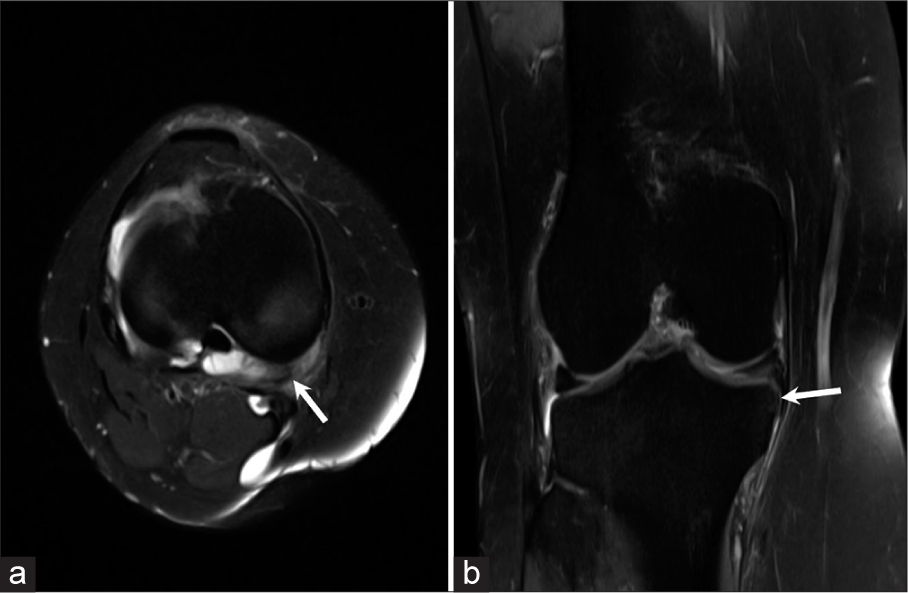
- (a) Axial proton density fat saturated (PDFS) image of a 35 years old patient with a history of trauma to the right knee shows a displaced medial meniscal fragment (arrow) arising from its posterior horn and body at 5 o’clock position. (b) Coronal proton density fat saturated (PDFS) image of the same patient shows the displaced fragment in the inferior coronary recess (horizontal arrow).
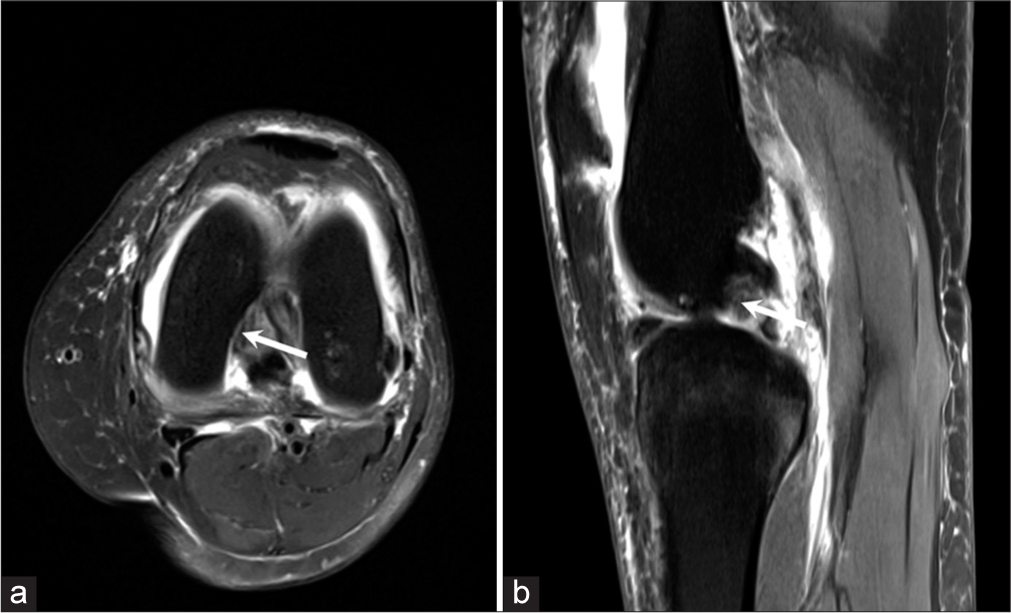
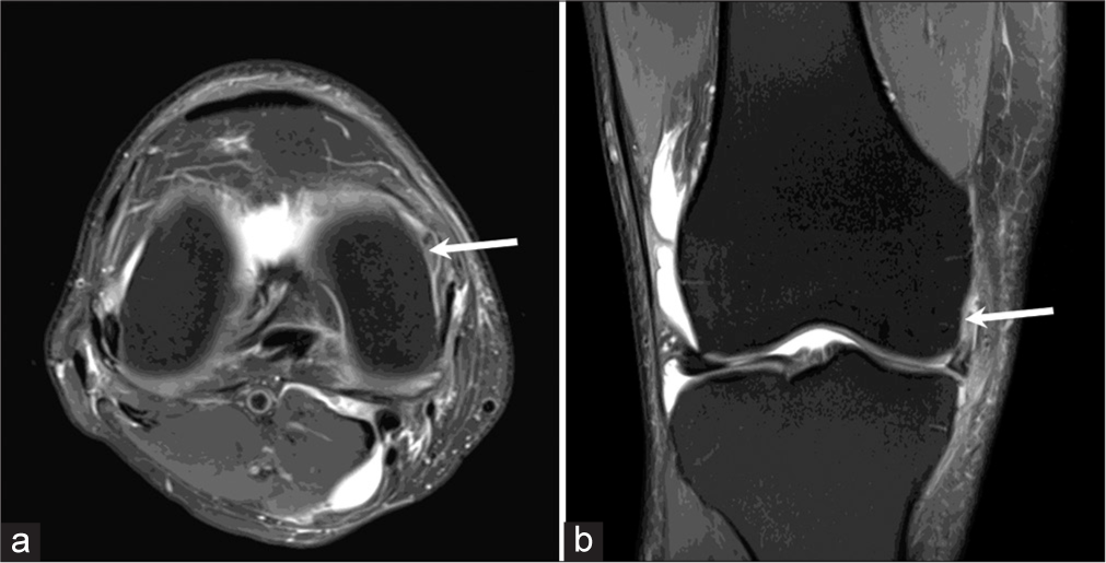
There was a displaced meniscal fragment arising from the anterior horn and body of medial meniscus at 9 o’clock position [Figure 4a]. The sagittal image showed the medial meniscal fragment displaced into the intercondylar region [Figure 4b].
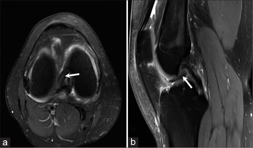
- (a) Axial proton density fat saturated (PDFS) image of a 39 years old patient with a history of trauma shows a displaced meniscal fragment arising from the anterior horn and body of medial meniscus at 9 o’clock position (arrow). (b) Sagittal proton density fat saturated (PDFS) image of the same patient shows the displaced medial meniscal fragment in the intercondylar region (arrow).
Figure 5a showed a displaced meniscal fragment arising from the body and posterior horn of medial meniscus of the right knee at 4 o’clock position. The coronal image shows a displaced fragment inferior to the medial meniscus [Figure 5b].
- (a) Axial proton density fat saturated (PDFS) image of a 45 years old patient with a history of pain in the medial aspect of right knee joint shows a displaced fragment arising from the body and posterior horn of medial meniscus at 4 o’clock position (arrow). (b) Coronal proton density fat saturated (PDFS) image of the same patient showing the displaced fragment inferior to the medial meniscus (‘Boomerang sign’) (arrow).
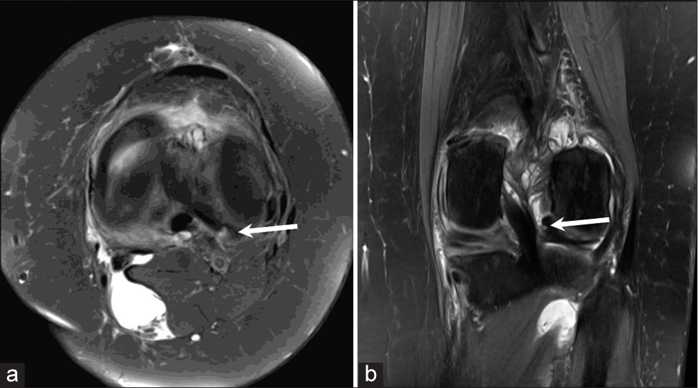
Axial Proton density fat saturated image demonstrates an displaced macerated medial meniscal fragment of the left knee at 9-10 o’clock position [Figure 6a]. The sagittal image shows the displaced fragment anterior to the posterior cruciate ligament [Figure 6b].
- (a) Axial proton density fat saturated (PDFS) image of a 43 years old patient with a history of trauma to the left knee shows a displaced macerated medial meniscal fragment at 9-10 o’clock position (arrow). (b) Sagittal proton density fat saturated (PDFS) image of the same patient shows the displaced meniscal fragment anterior to the posterior cruciate ligament (PCL) (arrow).
Figure 7a demonstrates a 40-year-old patient with history of fall, showing a displaced medial meniscal fragment at 3 o’clock position in the left knee. Coronal Proton density fat saturated image [Figure 7b] of the same patient shows the displaced medial meniscal fragment in the superior coronary recess.
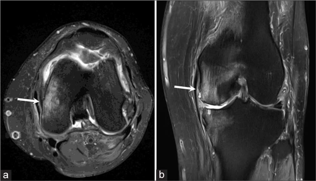
- (a) Axial proton density fat saturated (PDFS) image of a 40 years old patient with a history of fall shows the displaced medial meniscal fragment at 3 o’clock position in the left knee (arrow). (b) Coronal proton density fat saturated (PDFS) image of the same patient shows the displaced medial meniscal fragment in the superior coronary recess (arrow).
Axial Proton density fat saturated image of a patient with history of trauma to the left knee shows a displaced medial meniscal fragment at 7 o’clock position [Figure 8a]. The sagittal image of the same patient shows the displaced medial meniscal fragment lying in the posterior intercondylar region [Figure 8b].
- (a) Axial proton density fat saturated (PDFS) image of 35 years patient with a history of accident shows the displaced lateral meniscal fragment lying medially at 7 o’clock position in the left knee (arrow). (b) Sagittal proton density fat saturated (PDFS) image of the same patient shows the displaced medial meniscal fragment lying in the posterior intercondylar region (arrow).
Figure 9a demonstrates a patient with a history of pain in the right knee showing a displaced meniscal fragment arising from the posterior horn of medial meniscus at 2 o’clock position with coronal images of the same patient demonstrating the displaced meniscal fragment in the superior coronary recess [Figure 9b].
- (a) Axial proton density fat saturated (PDFS) image of a 47 year old patient with a history of pain in the right knee shows a displaced fragment arising from the posterior horn of medial meniscus at 2 o’clock position (arrow). (b) Coronal proton density fat saturated (PDFS) image of the same patient shows the displaced fragment in the superior coronary recess (arrow).
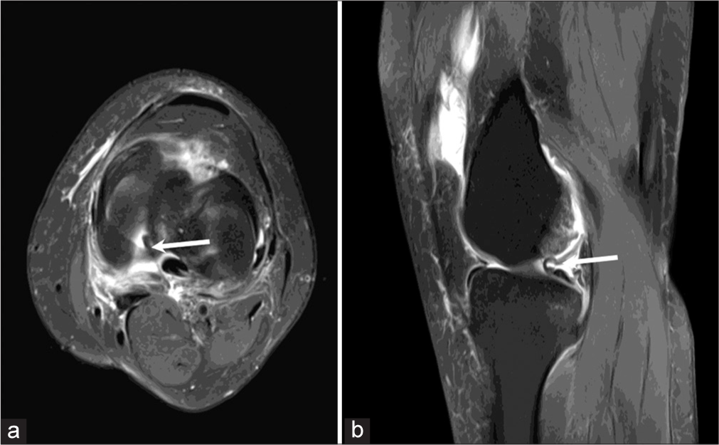
In a patient with sports injury to the left knee there was a displaced meniscal fragment arising from the posterior horn and body of lateral meniscus at 5 o’clock position [Figure 10a]. The coronal Proton density fat saturated images of the same patient shows the displaced lateral meniscal fragment in the intercondylar region [Figure 10b].
- (a) Axial proton density fat saturated (PDFS) image of a 34 years old patient with a history of sports injury to the left knee shows a displaced fragment arising from the posterior horn and body of the lateral meniscus at 5 o’clock position (arrow). (b) Coronal proton density fat saturated (PDFS) image of the same patient shows the displaced lateral meniscal fragment in the intercondylar region (arrow).
CONCLUSION
Using the clock face method for describing the displaced flap can help standardize radiological reporting and reduce descriptive errors while describing the position of the meniscal fragment. It can also help make reporting simpler and easier for the arthroscopists to decipher.
Ethical approval
All procedures performed in our study involving human participants were in accordance with the ethical standards of the Institutional Research Committee and with the 1964 Helsinki Declaration and its later amendments or comparable ethical standards.
Declaration of patient consent
Patient’s consent was not required as there are no patients in this study.
Conflicts of interest
There are no conflicts of interest.
Use of artificial intelligence (AI)-assisted technology for manuscript preparation
The authors confirm that there was no use of artificial intelligence (AI)-assisted technology for assisting in the writing or editing of the manuscript and no images were manipulated using AI.
Financial support and sponsorship
Nil.
References
- The International Society of Arthroscopy, Knee Surgery and Orthopaedic Sports Medicine classification of knee meniscus tears: Three-dimensional MRI and arthroscopy correlation. Eur Radiol. 2019;29:6372-84.
- [CrossRef] [PubMed] [Google Scholar]
- Meniscal tears: Current understanding, diagnosis, and management. Cureus. 2020;12:e8590.
- [CrossRef] [Google Scholar]
- The arthroscopic anatomy of symptomatic meniscal lesions. J Bone Joint Surg Br. 1990;72:628-33.
- [CrossRef] [PubMed] [Google Scholar]
- Illustrative review of knee meniscal tear patterns, repair and replacement options, and imaging evaluation. Clin Imaging. 2021;69:4-16.
- [CrossRef] [PubMed] [Google Scholar]
- Basic biology of the meniscus and response to injury. Instr Course Lect. 2000;49:189-93.
- [Google Scholar]
- Role of magnetic resonance imaging in the clinical management of the acutely locked knee. Skeletal Radiol. 2002;31:570-3.
- [CrossRef] [PubMed] [Google Scholar]
- The diagnosis of meniscus tears: The role of MRI and clinical examination. Clin Orthop Relat Res. 2007;455:123-33.
- [CrossRef] [PubMed] [Google Scholar]
- Meniscal tears with displaced fragments: Common patterns on magnetic resonance imaging. Skeletal Radiol. 2010;39:279-83.
- [CrossRef] [PubMed] [Google Scholar]


